Announcement

Collapse
No announcement yet.

Two Prong Flasher Auto Cancel Mod (Final)

Collapse
X
 
  • Filter
  • Time
  • Show
Clear All
new posts

  • #31
    Originally posted by Chuckster View Post
    I just received the relays and flasher I ordered , so I'm ready to give this a try. I think I have it all layed out, but I am a newbie when it comes to electrical. I bought some perf board, so as Cy suggested, I will mount the relays and flasher on the perf board. Any tips/advice on soldering the relatively thick 14 guage wire to those small leads on the relays? Should the leads remain straight, or is it better to bend them? I bought 2 sets of relays just in case I mess up.
    DO NOT bend the leads on the relays! They will snap off very easily. I used slightly smaller wire for the relays though - the stuff that came on little spools at Radio Shack. Tin the leads, and the wires, and make sure to leave plenty of bendy room on the wires. You can pre-bend them to make them fit better too.

    I suggest getting some spade connectors (like Geezer sells), as well as using a 90ยบ insulated connector to make a "Splice" into the fuse box connection. This will make it so you don't need to cut ANY wires on the harness.
    1980 XS850SG - Sold
    1981 XS1100LH Midnight Special (Sold) - purchased 9/29/08
    Fully Vetterized and Dynojet Kit added, Heated Grips, Truck-Lite LED headlight, Accel Coils, Irridium plugs, TKAT Fork Brace, XS850LH Final Drive & Black SS Brake lines from Chacal.
    Here's my web page devoted to my bike! XS/XJ User's Manuals there, and the XJ1100 Service Manual and both XS1100 Service manuals (free download!).

    Whether you think you can, or you think you cannot - You're right.
    -H. Ford

    Comment


    • #32
      Does anyone have pictures on how this is done. I am slow when it comes to wiring. Thanks
      1979 xs1100f
      New Fuse Box
      Progressive Shocks
      Gold Valve Emulator
      Dyna Coils
      Electronic Flasher
      Led Headlight
      Led Turn Signals
      4 Led Driving Lights
      2nd Gear Fix
      Auto Cam Tensioner
      Digital Dash
      Stainless Braided Lines
      R6 4 Piston Calipers
      Stainless Bolt Kit
      Maier Fairing
      Dyna Balancing Beads
      Spin On Oil Filter
      Stebel Nautilus Horn
      Plasti Dip Rims
      ISO Grips

      Comment


      • #33
        Originally posted by cywelchjr View Post
        Thanks to ELDR for researching how the stock flasher works which gave me the background needed to figure this out. If you

        are running LED turn signals you might consider his flasher module which does the same thing but is limited to LED lights

        only.

        This mod is really quite simple. It requires cutting two wires close to the flasher connector and wiring in two relays.

        First, get together the parts and tools you will need to do this. Here is the list of parts and tools that I used.

        Tools:

        Soldering Iron
        Needle Nose Pliers
        DVOM for Troubleshooting

        Parts:

        Heat Shrink Tubing
        Zip ties (cable ties)
        Mounting bases for cable ties
        10 Amp SPDT 12v 30 MA Relay Philmore part # BG-112
        2 Amp DPDT 1v 15 MA sensitive coil Relay NTE part # R40-11D2-12
        6" to 12" of 14 gauge stranded automotive wire


        Now, your going to start by cutting two wires close to the flasher plug, one you can cut as close as you want, the other

        you need to leave enough wire to strip, tin and solder another wire to.

        Cut the Yellow/Green wire, you can cut this as close to the connector as you want, as it will NOT get connected back to the

        connector, this is drive the 2 amp relay which will in turn drive the 10 amp relay. This is done because the 2 amp relay

        cannot handle normal bulbs, but the auto cancel unit can't drive the 10 amp relay.

        Next cut the Brown wire. Make sure to cut this far enough from the connector that you can connect another wire to both ends

        to extend the wire, you will be inserting the 10 amp relay in here to enable it to turn off the turn signals when the auto

        cancel unit tells it to.

        Determine where you want to locate the relays, I located mine just below where the flasher unit lives, and since they are

        really small and light I let them just hang by the wires, but you can fasten them in place with double sided tape or with

        zip ties if you wish.

        For the 2 amp relay find the switch side of the relay and connect the previous relay wire to one side switched setup for

        normally open operation, connect the other side to either the brown wire of the turn signal relay or as I did connect it to

        the downstream side of the turn signals fuse (I added it to the crimp connector). Connect the coil, one side to the

        Green/Yellow wire from the bikes harness, and the other side to a good ground, I used the same ground screw as I used for

        the other relay.

        Now, slide some heat shrink over one of the wires for the coil side of the 10 amp relay, but keep it back a ways so it

        doesn't shrink when you solder the wire. Solder the wire to the output of the 2 amp relay. Push the shrink tubing up and

        strink it into place. Connect the other wire to a good ground, I used the ground screw of the accessory connector.

        Find the leads for the switch side of the 10 amp relay, and find the normally closed side. The DVOM on ohms can be your

        friend here. Solder a short piece of wire to each side of the normally closed switch. Put shrink tubing over it and shrink

        it with a heat source (I use the soldering iron). Do the same with the coil side of the relay, keep track of which ones are

        which.

        Now, the last electrical part, solder the remaining two wires to the two brown wires, making sure to cover the solder

        joints with heat shrink. Fasten everything into place, I used the cable tie mounting bases and cable ties to mount things,

        and your ready to test.

        If you did everything right, you can turn on the turn signals before starting the bike, and then start the bike. The turn

        signals should not come on when the key is turned on. If they do, recheck your wiring job and parts, if everything is

        working properly the system comes up with the flasher inhibited.

        If this test passes, take it out for a test run, the auto cancel should work just like you have the stock flasher in place

        with the correct normal bulbs, whether you have the normal bulbs or LED bulbs.

        The Schematic:

        Originally posted by TheRev View Post
        Does anyone have pictures on how this is done. I am slow when it comes to wiring. Thanks
        Here ya go from the first page
        1980 XS1100G "Dolly G" Full Dresser (with a coat of many colors )
        1979 XS1100SF (stock-euro mods planned)
        1984 XV700L Virago (to be hot-modded)
        1983 XJ750MK Midnight Maxim (semi-restored DD)
        1977 XS650D ( patiently awaiting resto)

        Sometimes it takes a whole tank of gas before you can think straight.

        Comment


        • #34
          Can anyone who has done this mod post an actual pic of the units together? I am color blink and am having trouble figuring this out. I purchased all the necessary parts. Also, doe the engine need to be running to test the lights and signals? Thanks
          1979 xs1100f
          New Fuse Box
          Progressive Shocks
          Gold Valve Emulator
          Dyna Coils
          Electronic Flasher
          Led Headlight
          Led Turn Signals
          4 Led Driving Lights
          2nd Gear Fix
          Auto Cam Tensioner
          Digital Dash
          Stainless Braided Lines
          R6 4 Piston Calipers
          Stainless Bolt Kit
          Maier Fairing
          Dyna Balancing Beads
          Spin On Oil Filter
          Stebel Nautilus Horn
          Plasti Dip Rims
          ISO Grips

          Comment


          • #35
            Unfortunately Cy passed away a couple years ago before he really finalized this unit.
            Nathan
            KD9ARL

            μολὼν λαβέ

            1978 XS1100E
            K&N Filter
            #45 pilot Jet, #137.5 Main Jet
            OEM Exhaust
            ATK Fork Brace
            LED Dash lights
            Ammeter, Oil Pressure, Oil Temp, and Volt Meters

            Green Monster Coils
            SS Brake Lines
            Vision 550 Auto Tensioner

            In any moment of decision the best thing you can do is the right thing, the next best thing is the wrong thing, and the worst thing you can do is nothing.

            Theodore Roosevelt

            Comment


            • #36
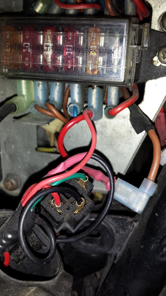
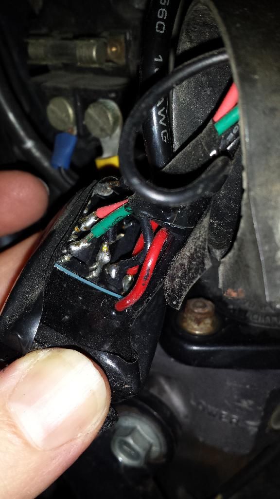
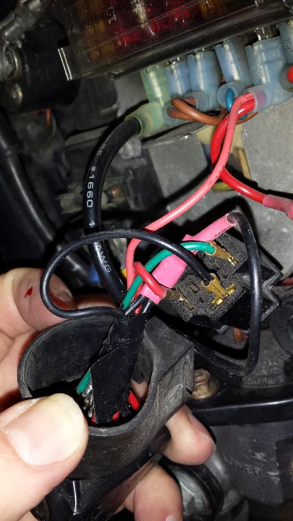
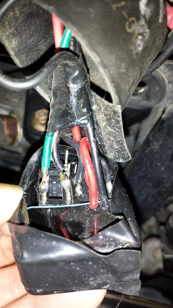
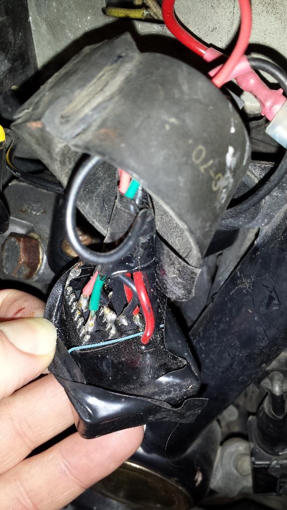
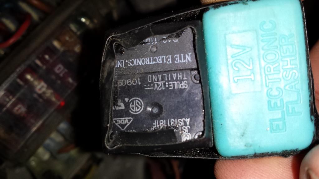
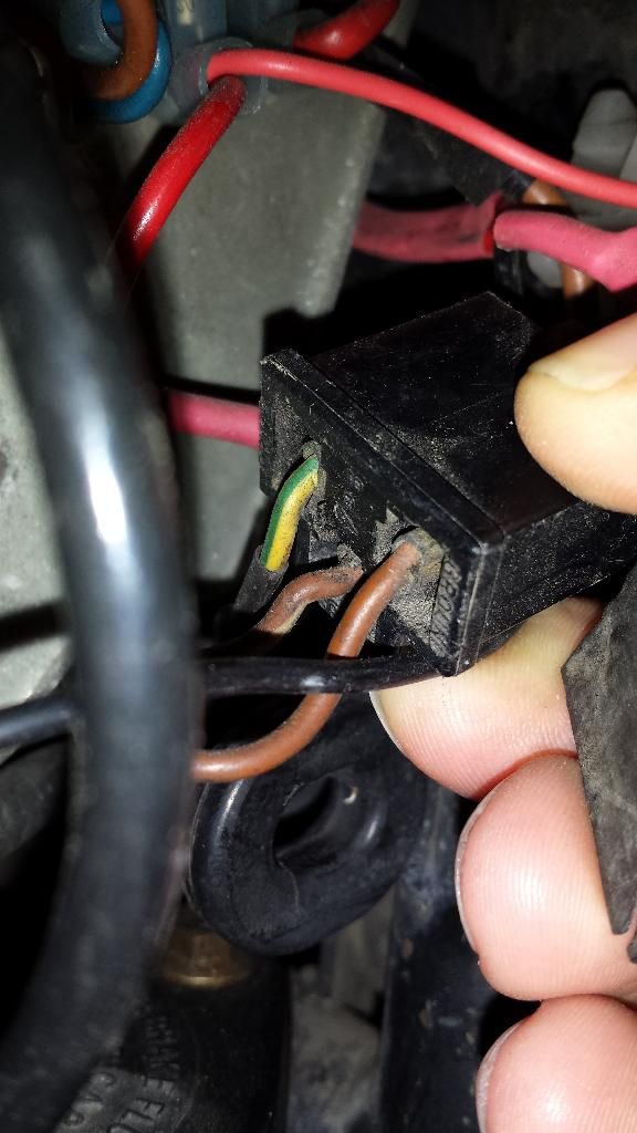
              I don't know how far anyone else has gone with this mod, but my unit has been working great since I installed it. Here are a few pictures of what is on my bike. The schematic above is pretty good, but I do suggest making one last tweak to it so you don't have to cut any of the OEM wires, making it 100% reversible.

              And to answer the question, the engine does not need to be running to test the flashers, but the bike needs to be moving to test the canceling feature.


              Last edited by CatatonicBug; 01-06-2014, 11:37 PM.
              1980 XS850SG - Sold
              1981 XS1100LH Midnight Special (Sold) - purchased 9/29/08
              Fully Vetterized and Dynojet Kit added, Heated Grips, Truck-Lite LED headlight, Accel Coils, Irridium plugs, TKAT Fork Brace, XS850LH Final Drive & Black SS Brake lines from Chacal.
              Here's my web page devoted to my bike! XS/XJ User's Manuals there, and the XJ1100 Service Manual and both XS1100 Service manuals (free download!).

              Whether you think you can, or you think you cannot - You're right.
              -H. Ford

              Comment


              • #37
                I am confused again. This diagram is difficult to understand. Both of the relays say 12v but not the amps. Which one is the 2 amp and which one is the 10 amp? Also, is the flasher connector the three prong unit that connects to the round flasher?

                Originally posted by Schming View Post
                Here ya go from the first page
                1979 xs1100f
                New Fuse Box
                Progressive Shocks
                Gold Valve Emulator
                Dyna Coils
                Electronic Flasher
                Led Headlight
                Led Turn Signals
                4 Led Driving Lights
                2nd Gear Fix
                Auto Cam Tensioner
                Digital Dash
                Stainless Braided Lines
                R6 4 Piston Calipers
                Stainless Bolt Kit
                Maier Fairing
                Dyna Balancing Beads
                Spin On Oil Filter
                Stebel Nautilus Horn
                Plasti Dip Rims
                ISO Grips

                Comment


                • #38
                  So please help me figure out the 10 amp relay. So I cut the brown wire coming off of the original flasher connector (the black plug coming off the harness) and solder that to the "common" pin on the 10 amp relay. Then I solder a short jumper wire to the "common" pin and onto the "NC" pin on the same relay?

                  Originally posted by CatatonicBug View Post
                  Cy - I finally got all the pieces together to make this mod happen this weekend, and failed miserably. The little tabs on the relays are so tiny that the weight of the wires ended up snapping them off! I found a socket for the 2A relay to prevent this from happening again. I couldn't find a socket for the 10A relay, but those pins are a little more robust.

                  I have ordered new relays (and a socket), but I'm a bit confused. When looking at the circuit diagram, I don't see the reason for a DPDT relay. It only uses half the pins. Wouldn't a SPDT relay work just fine? OFC, I'm mostly clueless when it comes to components.

                  The 2A relay has 8 pins on it, and they are numbered 1,4,6,8,9,11,13,16. According to the Data Sheet, 1 and 16 are the coil pins. If I'm reading it correctly, 4 and 13 are both common, then 6 and 11 are NC, and 8 and 9 are NO. Am I reading that correctly? If so, Which pins are the correct ones to use?

                  Would this be correct?

                  Pin 1 - spliced to yellow/green on the flasher plug
                  Pin 16 - to negative screw on accessory jack (convenient ground screw in the area)
                  Pin 4 - spliced to +12v wire on the Turn Signal fuse
                  Pin 8 - to coil pin on 10A relay

                  Then, for the 10A relay, there are 5 pins. Thankfully, they are well-marked. The 2 coil pins, a common pin, a NO pin, and a NC pin.

                  One coil pin is already connected to the 2A relay. The other goes to the same Neg terminal on the Accessory block.
                  The brown wire from the flasher connector gets cut, and re-connected to the Common pin and the NC pin. I used bullet connectors here instead of soldering, so I can remove the relays and put it back to stock if desired.
                  The NO pin is not used.

                  Can you verify that this is correct? What I plan to do is get this circuit all working, then pot the whole unit in a container of silicone to make it waterproof and vibration-resistant.
                  1979 xs1100f
                  New Fuse Box
                  Progressive Shocks
                  Gold Valve Emulator
                  Dyna Coils
                  Electronic Flasher
                  Led Headlight
                  Led Turn Signals
                  4 Led Driving Lights
                  2nd Gear Fix
                  Auto Cam Tensioner
                  Digital Dash
                  Stainless Braided Lines
                  R6 4 Piston Calipers
                  Stainless Bolt Kit
                  Maier Fairing
                  Dyna Balancing Beads
                  Spin On Oil Filter
                  Stebel Nautilus Horn
                  Plasti Dip Rims
                  ISO Grips

                  Comment


                  • #39
                    The relays will have their amp ratings on the housings. The smaller relay is used for the cancel function and was selected because it has a relatively low 'pull in' voltage/current, low enough to operate with the output from the OEM canceller unit.
                    Fast, Cheap, Reliable... Pick any two

                    '78E original owner - resto project
                    '78E ???? owner - Modder project FJ forks, 4-piston calipers F/R, 160/80-16 rear tire
                    '82 XJ rebuild project
                    '80SG restified, red SOLD
                    '79F parts...
                    '81H more parts...

                    Other current bikes:
                    '93 XL1200 Anniversary Sportster 85RWHP
                    '86 XL883/1200 Chopper
                    '82 XL1000 w/1450cc Buell, Baker 6-speed, in-progress project
                    Cage: '13 Mustang GT/CS with a few 'custom' touches
                    Yep, can't leave nuthin' alone...

                    Comment


                    • #40
                      Oh. I see you used spade connectors and pushed them into the appropriate slots in the flasher plug. Is that correct? Good thinking.

                      Originally posted by CatatonicBug View Post
                      I don't know how far anyone else has gone with this mod, but my unit has been working great since I installed it. Here are a few pictures of what is on my bike. The schematic above is pretty good, but I do suggest making one last tweak to it so you don't have to cut any of the OEM wires, making it 100% reversible.

                      And to answer the question, the engine does not need to be running to test the flashers, but the bike needs to be moving to test the canceling feature.


                      1979 xs1100f
                      New Fuse Box
                      Progressive Shocks
                      Gold Valve Emulator
                      Dyna Coils
                      Electronic Flasher
                      Led Headlight
                      Led Turn Signals
                      4 Led Driving Lights
                      2nd Gear Fix
                      Auto Cam Tensioner
                      Digital Dash
                      Stainless Braided Lines
                      R6 4 Piston Calipers
                      Stainless Bolt Kit
                      Maier Fairing
                      Dyna Balancing Beads
                      Spin On Oil Filter
                      Stebel Nautilus Horn
                      Plasti Dip Rims
                      ISO Grips

                      Comment


                      • #41
                        Ok I think I have most of the connections correct except for two things. I am stuck on the brown wire coming off the original plug. In your instructions it says connect it to the common pin on the 10 amp relay and the NC pin. How do I do that?

                        Also, when and where do I connect the electronic flasher? It has one black and one red wire.

                        Please help I would like to finish this mod tonight. Thanks

                        Originally posted by TheRev View Post
                        So please help me figure out the 10 amp relay. So I cut the brown wire coming off of the original flasher connector (the black plug coming off the harness) and solder that to the "common" pin on the 10 amp relay. Then I solder a short jumper wire to the "common" pin and onto the "NC" pin on the same relay?
                        1979 xs1100f
                        New Fuse Box
                        Progressive Shocks
                        Gold Valve Emulator
                        Dyna Coils
                        Electronic Flasher
                        Led Headlight
                        Led Turn Signals
                        4 Led Driving Lights
                        2nd Gear Fix
                        Auto Cam Tensioner
                        Digital Dash
                        Stainless Braided Lines
                        R6 4 Piston Calipers
                        Stainless Bolt Kit
                        Maier Fairing
                        Dyna Balancing Beads
                        Spin On Oil Filter
                        Stebel Nautilus Horn
                        Plasti Dip Rims
                        ISO Grips

                        Comment


                        • #42
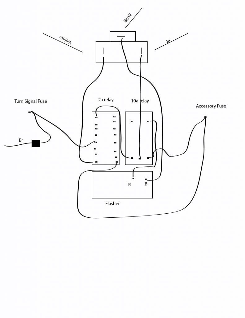
                          Here's another diagram, with the actual pinouts. Hopefully, it will help in the confusion.

                          1980 XS850SG - Sold
                          1981 XS1100LH Midnight Special (Sold) - purchased 9/29/08
                          Fully Vetterized and Dynojet Kit added, Heated Grips, Truck-Lite LED headlight, Accel Coils, Irridium plugs, TKAT Fork Brace, XS850LH Final Drive & Black SS Brake lines from Chacal.
                          Here's my web page devoted to my bike! XS/XJ User's Manuals there, and the XJ1100 Service Manual and both XS1100 Service manuals (free download!).

                          Whether you think you can, or you think you cannot - You're right.
                          -H. Ford

                          Comment


                          • #43
                            So the brown wire from the plug gets soldered to the Common pin only? Or am i missing something? Thanks
                            1979 xs1100f
                            New Fuse Box
                            Progressive Shocks
                            Gold Valve Emulator
                            Dyna Coils
                            Electronic Flasher
                            Led Headlight
                            Led Turn Signals
                            4 Led Driving Lights
                            2nd Gear Fix
                            Auto Cam Tensioner
                            Digital Dash
                            Stainless Braided Lines
                            R6 4 Piston Calipers
                            Stainless Bolt Kit
                            Maier Fairing
                            Dyna Balancing Beads
                            Spin On Oil Filter
                            Stebel Nautilus Horn
                            Plasti Dip Rims
                            ISO Grips

                            Comment


                            • #44
                              Yes. I soldered a wire to the pin and put a spade terminal to the other end, then plugged the spade terminal into the flasher plug.
                              1980 XS850SG - Sold
                              1981 XS1100LH Midnight Special (Sold) - purchased 9/29/08
                              Fully Vetterized and Dynojet Kit added, Heated Grips, Truck-Lite LED headlight, Accel Coils, Irridium plugs, TKAT Fork Brace, XS850LH Final Drive & Black SS Brake lines from Chacal.
                              Here's my web page devoted to my bike! XS/XJ User's Manuals there, and the XJ1100 Service Manual and both XS1100 Service manuals (free download!).

                              Whether you think you can, or you think you cannot - You're right.
                              -H. Ford

                              Comment

                              Working...
                              X