Announcement

Collapse
No announcement yet.

Alternative Alternator Options

Collapse
X
 
  • Filter
  • Time
  • Show
Clear All
new posts

  • #16
    Yeah, I don't think you're going to see a CPS or Hz below 200, and I suspect higher. If you only use one diode (for a half-wave output), that would cut it in half to 100, but would still exceed the capabilities of the meter. You would get a reading, but it wouldn't match the calibration/meter scale so you couldn't really tell what you have.

    Somebody with an oscilloscope could quickly tell you what you have...
    Fast, Cheap, Reliable... Pick any two

    '78E original owner - resto project
    '78E ???? owner - Modder project FJ forks, 4-piston calipers F/R, 160/80-16 rear tire
    '82 XJ rebuild project
    '80SG restified, red SOLD
    '79F parts...
    '81H more parts...

    Other current bikes:
    '93 XL1200 Anniversary Sportster 85RWHP
    '86 XL883/1200 Chopper
    '82 XL1000 w/1450cc Buell, Baker 6-speed, in-progress project
    Cage: '13 Mustang GT/CS with a few 'custom' touches
    Yep, can't leave nuthin' alone...

    Comment


    • #17
      More fun thoughts!?

      Okay, went to the local ALT rebuilders, but their resident GURU was not in today, his Saturday shift rotation is NEXT weekend...should have called them first, some 25miles across the metroplex to the big city of Va. Bch!

      Been doing some more research. I've found some NEW style 1 wire alts, ie. the Chevy MINI-Alt, Denso Street Rod Race type, 50 amp capacity, but it doesn't have a tach connection. It's dimensions are almost PERFECT at about 4" diameter, 4.5" length plus PULLY, and only 5 lbs!

      I've been thinking about what was suggested earlier about leaving the OEM one in place to use it's tach signal. Question is what would happen to the OEM reg/rect and ALT if they were left in place/active, and a 1 wire self exciting ALT were wired into the HARNESS=main battery cable?
      The 1 wire unit senses the system voltage thru that 1 wire, and IF the OEM ALT were cranking out power, then the internal VR of the 1-wire Alt would probably shut down or greatly reduce the output, and therefore probably also the amperage???

      Also, no way of attaching the DRIVE/Crankshaft pully with the OEM alt in position! SO....it looks like the OEM Alt and Casing cover would still need to be removed, so as not damage them in case of returning to OEM, and being able to access the crankshaft/Rotor assembly to mount the extra ALT mounting bracket(s) as well as the crank pulley.
      I'll be getting with the ALT GURU via mail, or email this coming week, along with meeting with him in person next Saturday IF he thinks we can come up with some solutions to keep the electronic Tach and find an ALT small enough to fit where it can be placed...have taken some photos, will post once I make some "Paint" additions to them for diagramming the location of parts!

      Stay Tuned! T.C.
      T. C. Gresham
      81SH "Godzilla" . . .1179cc super-rat.
      79SF "The Teacher" . . .basket case!
      History shows again and again,
      How nature points out the folly of men!

      Comment


      • #18
        Interested to see where this goes......
        Nathan
        KD9ARL

        μολὼν λαβέ

        1978 XS1100E
        K&N Filter
        #45 pilot Jet, #137.5 Main Jet
        OEM Exhaust
        ATK Fork Brace
        LED Dash lights
        Ammeter, Oil Pressure, Oil Temp, and Volt Meters

        Green Monster Coils
        SS Brake Lines
        Vision 550 Auto Tensioner

        In any moment of decision the best thing you can do is the right thing, the next best thing is the wrong thing, and the worst thing you can do is nothing.

        Theodore Roosevelt

        Comment


        • #19
          Originally posted by TopCatGr58 View Post
          Been doing some more research. I've found some NEW style 1 wire alts, ie. the Chevy MINI-Alt, Denso Street Rod Race type, 50 amp capacity, but it doesn't have a tach connection. It's dimensions are almost PERFECT at about 4" diameter, 4.5" length plus PULLY, and only 5 lbs!
          One thing I'd be sure to ask is what is it's operating range as far as minimum/maximum rpm and what's the best for usable output. That will give you an idea about what ratio you'll need for the drive.

          As far as getting a 'tach signal', that wouldn't be that tough. Open it up, and tap off one of the stator wires ahead of the rectifier and there's your signal. Now, you'll still have the issue of frequency matching to get the tach to read right, but you'll have something to work with.

          While you're there, ask the Guru if he's aware of any small permanent-magnet type alternators with a decent output; I still think this type would be the easiest to adapt if you could find one with a small enough diameter.
          Last edited by crazy steve; 02-05-2011, 07:08 PM.
          Fast, Cheap, Reliable... Pick any two

          '78E original owner - resto project
          '78E ???? owner - Modder project FJ forks, 4-piston calipers F/R, 160/80-16 rear tire
          '82 XJ rebuild project
          '80SG restified, red SOLD
          '79F parts...
          '81H more parts...

          Other current bikes:
          '93 XL1200 Anniversary Sportster 85RWHP
          '86 XL883/1200 Chopper
          '82 XL1000 w/1450cc Buell, Baker 6-speed, in-progress project
          Cage: '13 Mustang GT/CS with a few 'custom' touches
          Yep, can't leave nuthin' alone...

          Comment


          • #20
            Hey Steve and folks,

            I found a permanent Magnet ALT on Ebay, small enough, but was limited in it's speed ~2000rpm, and output...<20amps!

            Okay, more thinking has been done, let's see what sticks!?

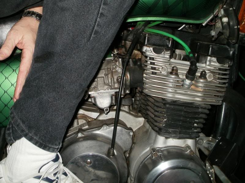
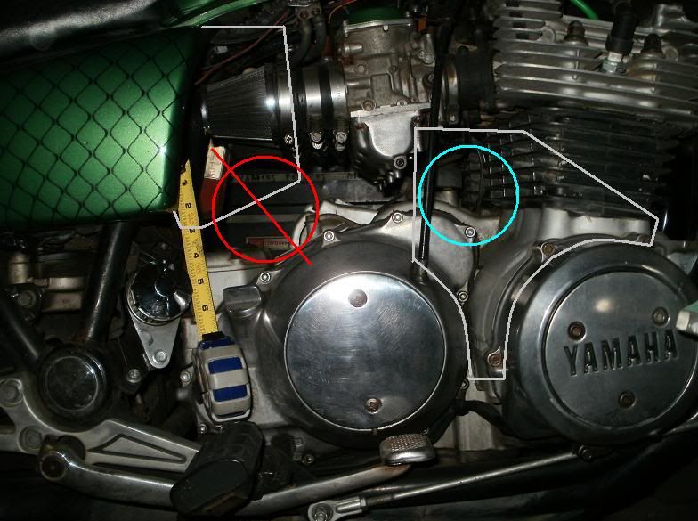
            This first image shows a sideview of my bike, I added the outline of the OEM airbox, so can see not much room there. The space just behind the head and infront of the clutch cable looks prime, for keeping it away from our legs, and has the 4" of diameter space needed for the mini-alt.


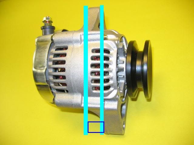
            Here's a photo of the possible ALT, note that its mounting sections are almost midway, and depending on the location of the drive pulley, it could be mounted to the plate one of two ways, the darker blue would be a spacer if needed!


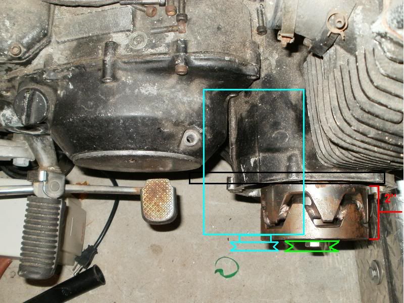
            Next image...pardon the junkier bike..my 79SF basket case still in baskets!
            This shows mounting the Pulley onto the end of Rotor, with the rotor exposed, I think it could be difficult to find a tapered shaft drive pulley!


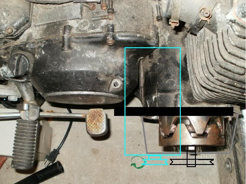
            This image shows keeping the OEM ALT cover/innards....would require drilling a hole in the middle of the case to allow the use of a longer bolt and spacer to mount the Pulley on the outside of the case.


            The thoughts about this would be to provide a key switched steady 12 volt power to the FIELD coil, but do NOT connect any of the 3 charging Stator wires to the system. Just use the field coil energy to create the already synched tach pulse feed for the tach, that way the External Alt can do all the work of generating all of the 50Amps power for the bike, the OEM Reg/Rect also be disconnected.

            The downside is of course drilling the OEM ALT casing. I would think a simple oiled felt washer around the pulley shaft would be enough to keep out dust and water if we got caught in the rain.

            Also a thin heat/rain guard cover could be fashioned from thin SS plate or Aluminum plate to fit over/around the new ALT again for protection against the occasional rain storm! Would possibly also fashion a similar cover for the exposed pulleys/belt!

            Okay, thoughts, ideas??

            I do like the thought of tapping from one of the windings of the New Alt for the tach signal, but like you said, finding the right RPM/frequency to match the OEM and at the same time the right sizes for the Drive to Alt Pulley ratios to have it create power at moderatley low RPM. The other photos I've seen show it has 2 small wire plugs to it aside from the large battery plug...allegedly for the ALT sensor/bulb on an car, as well as a switched 12V power feed to provide the field coils power sooner to help generate power at/below the Self Exciteable RPM!?

            T.C.
            T. C. Gresham
            81SH "Godzilla" . . .1179cc super-rat.
            79SF "The Teacher" . . .basket case!
            History shows again and again,
            How nature points out the folly of men!

            Comment


            • #21
              Originally posted by TopCatGr58 View Post
              I found a permanent Magnet ALT on Ebay, small enough, but was limited in it's speed ~2000rpm, and output...<20amps!
              Don't discount that just yet; the rpm thing can be addressed with drive ratio if it would have usable output in 'normal' engine rpm range (say, 2K to 5K). If the size is more advantagous, it's shortcomings might be worth overlooking. Got a link to that unit? Another possibility is being able to 'switch' the extra alternator in/out of the circuit if the extra amps aren't needed. Fitting an ammeter would tell you when you needed it...
              Fast, Cheap, Reliable... Pick any two

              '78E original owner - resto project
              '78E ???? owner - Modder project FJ forks, 4-piston calipers F/R, 160/80-16 rear tire
              '82 XJ rebuild project
              '80SG restified, red SOLD
              '79F parts...
              '81H more parts...

              Other current bikes:
              '93 XL1200 Anniversary Sportster 85RWHP
              '86 XL883/1200 Chopper
              '82 XL1000 w/1450cc Buell, Baker 6-speed, in-progress project
              Cage: '13 Mustang GT/CS with a few 'custom' touches
              Yep, can't leave nuthin' alone...

              Comment


              • #22
                My bad, that Perm. magnet only put out 4 AMPS!!

                Here's the Ebay:
                http://cgi.ebay.com/ebaymotors/Small...mZ110633005741

                Okay, a closer look at our Stator and the Rotor reveals the following.
                36 segments, divided into 3 phases, 12 segments...and I think it requires 2 segments to make one POLE. So...6 actual poles per phase segment per revolution.

                There are large 6 divisions on the ROTOR, 6 smaller ones closer to the bolt head, but 6 points to either end of the "V" shapes. So...I'm thinking that it will break the field six times in 1 revolution, and with

                So...6 divisions into 6 poles should result in 36 pulses per revolution, that's 36,000 per minute at 1000 engine rpm, but back down to 36 hz frequency for 1000 engine rpm.

                I sent an email to the ALT GURU at the shop I visited, will have to wait till next week probably before I hear anything from them.

                Steve, I'm trying to make this project as simple as possible, more of a bolt on and disconnect wires/plugs type of mod that I can for the masses, so trying to add extra cut out/in switches and such for a permanent magnet type ALT doesn't appeal to me.

                Did what I say about energizing the field coil, but having the stator wires disconnected just to get the Tach single phase tap signal sound feasible!

                Just not sure how willing folks would be to drill their Alt Case to be able to mount the extension and longer bolt, vs. just removing the OEM parts, mounting the pulley to the ROTOR, and having to either get an aftermarket electronic tach, vs. having to wire a tap to the Ext. Alt internal wires??

                T.C.
                T. C. Gresham
                81SH "Godzilla" . . .1179cc super-rat.
                79SF "The Teacher" . . .basket case!
                History shows again and again,
                How nature points out the folly of men!

                Comment


                • #23
                  Originally posted by TopCatGr58 View Post
                  Okay, a closer look at our Stator and the Rotor reveals the following.
                  36 segments, divided into 3 phases, 12 segments...and I think it requires 2 segments to make one POLE. So...6 actual poles per phase segment per revolution.

                  There are large 6 divisions on the ROTOR, 6 smaller ones closer to the bolt head, but 6 points to either end of the "V" shapes. So...I'm thinking that it will break the field six times in 1 revolution, and with

                  So...6 divisions into 6 poles should result in 36 pulses per revolution, that's 36,000 per minute at 1000 engine rpm, but back down to 36 hz frequency for 1000 engine rpm..
                  Hard to say how the stator is laid out; somebody who is more familar with vehicle alternators could answer that better. But the rotor has 12 poles; each 'point' represents a pole. That's why the two halves are separated by that non-ferrous 'ring' that joins them. And your Hz calc is off; 6 x 12 x 1000 = 72000 cycles per 1K rpm. To get Hertz (aka cycles per second), you divide by 60 (60 seconds in a minute) and that gives you 1200 Hz @ 1K rpm. Hz is directly proportional to rpm; double the rpm, and the frequency doubles.

                  To be honest, I don't see any way to do this without having to make at least a several hundred $ investment...
                  Fast, Cheap, Reliable... Pick any two

                  '78E original owner - resto project
                  '78E ???? owner - Modder project FJ forks, 4-piston calipers F/R, 160/80-16 rear tire
                  '82 XJ rebuild project
                  '80SG restified, red SOLD
                  '79F parts...
                  '81H more parts...

                  Other current bikes:
                  '93 XL1200 Anniversary Sportster 85RWHP
                  '86 XL883/1200 Chopper
                  '82 XL1000 w/1450cc Buell, Baker 6-speed, in-progress project
                  Cage: '13 Mustang GT/CS with a few 'custom' touches
                  Yep, can't leave nuthin' alone...

                  Comment


                  • #24
                    pm alternator

                    I don't know about modifying a tach but the only reliable charging system is going to be of the permanent magnet variety. No brushes to wear and a source of juice that doesn't fluctuate such as the battery excited setup. The simpler the setup the less that can break. Anyone try this?

                    http://www.xs650.com/forum/showthread.php?t=5536&page=3

                    I'm definitely going to look into it. No battery. No starter. No worries

                    Comment


                    • #25
                      Hey Steve,

                      Thanks for that....I'm not an electronics guru, so glad to understand that each segment is a pole. I'm just hoping that the ALT Guru will be able to tell me what the Hz rate for auto alts is, and whether we can get it to match ours, and have the alt spinning at a decent speed to provide a good charging rate at close to idle speed.

                      Trash, the 650's have been made for a lot longer time than the 1100's, and are supported by many more after market manufacturers as well. But the bike companies(Yamaha) seemed to have purposely made them very proprietary for each model, so that complicated parts like this do not fit onto other models very easily or without a lot of modification=WORK=$$.

                      I'm just trying to find a relatively cost effective process...these mini-alts are on ebay for $75.00. I will most likely be involved in making the mounting plates from 1/4" or 5/16" plate aluminum, just cutting it out with a metal cutting band saw, and then a template to make/match the bolt hole patterns of the OEM alt. The plate material shouldn't be much more than $20.00. Then there's just the crank Pulley, the belt, a 10ga ~2 foot long charging wire, so I don't necessarily see this thing running anywhere close to or over $200.00!

                      T.C.
                      T. C. Gresham
                      81SH "Godzilla" . . .1179cc super-rat.
                      79SF "The Teacher" . . .basket case!
                      History shows again and again,
                      How nature points out the folly of men!

                      Comment


                      • #26
                        Originally posted by TopCatGr58 View Post
                        I'm just trying to find a relatively cost effective process...these mini-alts are on ebay for $75.00. I will most likely be involved in making the mounting plates from 1/4" or 5/16" plate aluminum, just cutting it out with a metal cutting band saw, and then a template to make/match the bolt hole patterns of the OEM alt. The plate material shouldn't be much more than $20.00. Then there's just the crank Pulley, the belt, a 10ga ~2 foot long charging wire, so I don't necessarily see this thing running anywhere close to or over $200.00!

                        T.C.
                        T.C., my electronics knowlege is spotty at best, as I worked as an electrician. But I was taught the theory well (you needed to know how this stuff worked if you had to troubleshoot a circuit) and that's the same even if the application is much different sometimes...

                        Where I see the real difficulty (ignoring the tach issue) is driving the alternator. Using a belt presents several problems; first, attaching a pulley to the motor. I'll be amazed if you don't need some sort of custom pulley or at least adaptor to allow you to fit a off-the-shelf pulley to the end of the crankshaft. That's going to need to be a pretty stout piece and there's not a lot of room to fit it. If you use the rotor bolt to retain it, I see bolt failures due to the side loads as noted below.

                        Next, getting the right pulley sizes for proper rpm. If you run small pulleys and a v- or serpentine-type belt (and I don't see any way not to use small pulleys), the belt is going to have to be run pretty tight to avoid slipping (small pulley = less surface area for the belt to grip) so you'll be putting a pretty big side-load on the crankshaft snout that it wasn't designed for. Maybe a problem, maybe not. Removing the stock alternator altogether and moving the pulley closer in helps with the 'leverage' on the crank but complicates this in other ways. Either way, you're loading the crank in ways it wasn't designed for. Another consideration is the new alternator mount; a heavy side load from belt tension will put stress on the mount. I really think you would have to anchor both ends of the alternator to prevent mount flex, and that'll be tough on the non-drive end.

                        Now, you can eliminate some of this by using some sort of positive drive. A gear drive would work, but big $$, and you'd have to figure out a way to keep it lubed. A chain drive would be cheaper, but you still have the lube problem and you'd have to make sure the chain could take the high rpms involved (a chain flying off at 8000 rpm would not be good..). A cogged belt would be best (low rotating mass, so it could take the rpms), no lube needed, only needs to be tight enough to keep the teeth engaged, and relatively commonly available (used in NASCAR, other racing). But not cheap; a drive system like this I expect would set you back at least $100, if not much more. These are also wider than a conventional belt drive, so now you're back to space considerations.
                        The electrical issues I see as the least of the problems; actually getting the thing mounted is what will be hard. Maybe I'm too much of a pessimist...
                        Fast, Cheap, Reliable... Pick any two

                        '78E original owner - resto project
                        '78E ???? owner - Modder project FJ forks, 4-piston calipers F/R, 160/80-16 rear tire
                        '82 XJ rebuild project
                        '80SG restified, red SOLD
                        '79F parts...
                        '81H more parts...

                        Other current bikes:
                        '93 XL1200 Anniversary Sportster 85RWHP
                        '86 XL883/1200 Chopper
                        '82 XL1000 w/1450cc Buell, Baker 6-speed, in-progress project
                        Cage: '13 Mustang GT/CS with a few 'custom' touches
                        Yep, can't leave nuthin' alone...

                        Comment


                        • #27
                          Originally posted by TRASH View Post
                          I don't know about modifying a tach but the only reliable charging system is going to be of the permanent magnet variety. No brushes to wear and a source of juice that doesn't fluctuate such as the battery excited setup. The simpler the setup the less that can break. Anyone try this?

                          http://www.xs650.com/forum/showthread.php?t=5536&page=3

                          I'm definitely going to look into it. No battery. No starter. No worries
                          I suggested this early-on, but one of the problems here is finding one that at least matches the OEM unit's 20 amp output. The whole point of this thread is to get more output, as the original unit is marginal if you try to add any loads.

                          And note that you still need a rectifier/regulator and battery even with the permanent-magnet type (or at least a 'battery eliminator' such as they used to use on some Brit bikes, although I'm not sure that would work here). The regulator needs a 'reference load' to adjust output voltage to. The stock XS alternator has no brushes, so there's no wearing parts and is generally very reliable if not mistreated or has bad connections. Only the XJ has the brushes...
                          Fast, Cheap, Reliable... Pick any two

                          '78E original owner - resto project
                          '78E ???? owner - Modder project FJ forks, 4-piston calipers F/R, 160/80-16 rear tire
                          '82 XJ rebuild project
                          '80SG restified, red SOLD
                          '79F parts...
                          '81H more parts...

                          Other current bikes:
                          '93 XL1200 Anniversary Sportster 85RWHP
                          '86 XL883/1200 Chopper
                          '82 XL1000 w/1450cc Buell, Baker 6-speed, in-progress project
                          Cage: '13 Mustang GT/CS with a few 'custom' touches
                          Yep, can't leave nuthin' alone...

                          Comment


                          • #28
                            It's okay to be a &quot;PISS&quot;amist!

                            Hey Steve,

                            Yours and others input is why I started this thread, to try to suss out the pros, cons, etc. for something like this!

                            The specs on the Mini-Alt state that it's a low drag unit...it's designed for Rod/Race type applications, but I've read about others using it in small cars for replacing their older GEN types, etc.!

                            Looking at the mounting brackets on the unit, I saw that they were near the middle, and so the stress on that area would be greater with the increased distant between the belt/pulley and the mounts. I had thought about an additional bracket somehow to the END of the ALT, or at least to the same mounting points, but to another location on the engine to provide a tripod type support? Being low drag design is part of what I was hoping for in not having to have the belt as tight.

                            Putting the pulley on the END of the shaft/rotor was more of what I had planned which would allow the ALT to also stick out farther from the engine away from the carbs/heads, to allow it's pulley to be in line with the crank one positioned on the END of the shaft/Rotor. Having the drive pulley closer to the engine case would require the ALT to be either much shorter or positioned under the carbs and behind the heads, but farther inwards. The bearings are under stress from the pistons, so I figured that the pulley will put similar types of stress there, thought it would be okay.

                            I've searched for motorcycle alts, and ones I've found for like the GL1500 or so are close to $300.00, and they use what looks like a spline drive, the engine is designed for them and their fitment, and I didn't find their output specs anyways..but just seemed like they would be just as much if not more of a pain to try to MOD to fit our bikes.

                            I've never had to take the crankshaft bolt off, but I think I remember folks saying that it's normal right hand threads...the reverse spin of the engine helps to keep it tight! I would think either some blue locktite would be enough along with the lock washer to keep a pulley secure. I know auto pulleys have keys to keep them from spinning, but I just don't think that there will be that much stress. I could be wrong? Just now thinking about it, a couple of "L" shaped brackets could be bolted to the Drive pulley, with other bolts coming thru the bracket into the slots of the rotor to help secure it from spinning loose!?

                            I haven't checked the available lengths of the v-belts, hoping that I can find one short enough. With just the Drive belt and ALt pulley, they will have a good 180 degrees of contact, some Auto Alts share with other devices, and the belt often comes from a much wider angle and have less actual contact. The longer pulley/belt contact area/distance should also allow for less actual tension and stress and still provide good friction to prevent slippage.

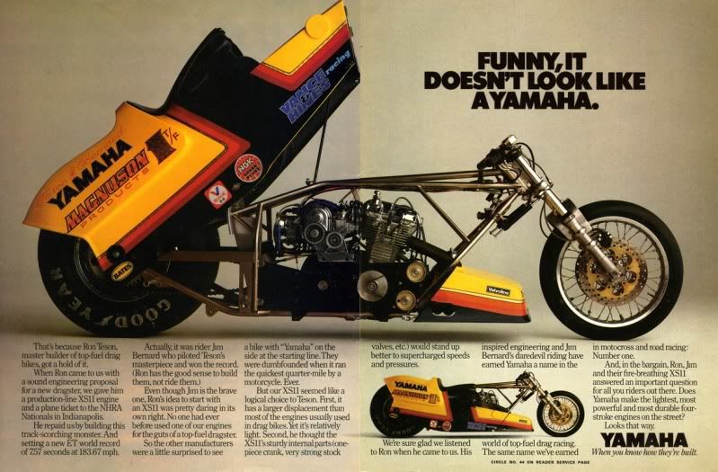
                            Just for fun, here's a pic of a "slightly" modified XS11, it has quite a few pulleys on it!

                            T.C.
                            T. C. Gresham
                            81SH "Godzilla" . . .1179cc super-rat.
                            79SF "The Teacher" . . .basket case!
                            History shows again and again,
                            How nature points out the folly of men!

                            Comment


                            • #29
                              Would the reverse rotation of the XS1100 engine affect the rotation of the alternator? Would you have to find an alternator that rotated the correct direction or would it matter?

                              I think the strongest mount would be a plate that uses all the alt cover bolts. Trace the cover inside and out, cut out the inside, and cut the outside to include the alternator. Trim the corrosponding thickness from the XS alt cover (and notch the cover for the belt to pass through).
                              Pat Kelly
                              <p-lkelly@sbcglobal.net>

                              1978 XS1100E (The Force)
                              1980 XS1100LG (The Dark Side)
                              2007 Dodge Ram 2500 quad-cab long-bed (Wifes ride)
                              1999 Suburban (The Ship)
                              1994 Dodge Spirit (Son #1)
                              1968 F100 (Valentine)

                              "No one is totally useless. They can always be used as a bad example"

                              Comment


                              • #30
                                Another thought on the tach.
                                An aftermarket tach that reads the pulse from the one of the coils. There must be one that accounts for a 4 cyl engine with a wasted spark system.
                                Pat Kelly
                                <p-lkelly@sbcglobal.net>

                                1978 XS1100E (The Force)
                                1980 XS1100LG (The Dark Side)
                                2007 Dodge Ram 2500 quad-cab long-bed (Wifes ride)
                                1999 Suburban (The Ship)
                                1994 Dodge Spirit (Son #1)
                                1968 F100 (Valentine)

                                "No one is totally useless. They can always be used as a bad example"

                                Comment

                                Working...
                                X