Announcement

Collapse
No announcement yet.

Alternative Alternator Options

Collapse
X
 
  • Filter
  • Time
  • Show
Clear All
new posts

  • #31
    Hey Pat,

    Thanks for taking time from your busy trucking schedule!
    The backwards rotation only affects the cooling, and so I just have to make sure to be able to get a reversible fan blade for it. The other electronic tachs that work off of the ignition coil trigger are available from MikesXS for a modest price, but they are not the same size as OEM! This is partly why I'm hoping to be able to keep the OEM tach/trigger system!

    T.C.

    Tachometer - Electronic Electronic Tachometer (operates from Ignition pulses) 0-12,000 RPM
    1.9 Dia. (48mm.), Black Face Tach functions only with single dual
    output type ignition coils - (80-84 factory Tci). Part #03-0675$69.00 USD Ea
    One of our PAIR of output coils are DUAL OUTPUT, and would only need to be connected to one of them, same wasted spark design, same spark count.
    T. C. Gresham
    81SH "Godzilla" . . .1179cc super-rat.
    79SF "The Teacher" . . .basket case!
    History shows again and again,
    How nature points out the folly of men!

    Comment


    • #32
      Originally posted by TopCatGr58 View Post
      Hey Pat,

      Thanks for taking time from your busy trucking schedule!
      The backwards rotation only affects the cooling, and so I just have to make sure to be able to get a reversible fan blade for it. The other electronic tachs that work off of the ignition coil trigger are available from MikesXS for a modest price, but they are not the same size as OEM! This is partly why I'm hoping to be able to keep the OEM tach/trigger system!

      T.C.


      One of our PAIR of output coils are DUAL OUTPUT, and would only need to be connected to one of them, same wasted spark design, same spark count.
      If we can find a way to determine the frequency of the stock alternator, vs the installed freq of a higher output replacement I would be willing to do some research into a frequency conversion unit. I can't really see it as being too complex, although it might require opening the tach to do it (might involve modification after the conversion to digital inside the tach, which I'm sure happens if AC conversion is too difficult).
      Cy

      1980 XS1100G (Brutus) w/81H Engine
      Duplicolor Mirage Paint Job (Purple/Green)
      Vetter Windjammer IV
      Vetter hard bags & Trunk
      OEM Luggage Rack
      Jardine Spaghetti 4-2 exhaust system
      Spade Fuse Box
      Turn Signal Auto Cancel Mod
      750 FD Mod
      TC Spin on Oil Filter Adapter (temp removed)
      XJ1100 Front Footpegs
      XJ1100 Shocks

      I was always taught to respect my elders, but it keeps getting harder to find one.

      Comment


      • #33
        Cy, when I took one of my tachs apart to try to fix it I took a look at the circuit board.

        I Google-checked the numbers on the single TTL chip, 6 or 8 pin, I don't remember and it might even be a proprietary chip for Yamaha, but I didn't save the numbers. I do have a spare tach I can pull apart to check the board again.

        From the numbers I did find on the chip the search turned up pulse counters to DC converters. Some discrete components drive the tach needle motor itself.

        The drive motor is fragile. If you take it apart and manage to get it back together again without breaking the hair-like wires, disturbing the magnets or mis-adjusting the armature bearings it won't be calibrated even if it works.
        -- Scott
        _____
        ♬
        2004 ST1300A: No name... yet
        1982 XJ1100J: "Baby" SS Brakes, '850 FD, ACCT
        1980 XS1100G: "Columbo" SS Brakes, '850 FD, ACCT
        1979 XS1100SF: "Bush" W.I.P.
        1979 XS1100F: parts
        2018 Heritage Softail Classic 117 FLHCS SE: "Nanuk" It's DEAD, it's not just resting. It is an EX cycle.
        ♬

        Comment


        • #34
          not sure if this helps u out,
          theres a bit of a write up on the uk site
          regarding the tacho here

          http://www.benefiscal.co.uk/forum/in...p?topic=7926.0

          theres a part number for the chip i think ur talking about there.

          hope his helps.
          pete


          new owner of
          08 gen2 hayabusa


          former owner
          1981 xs1100 RH (aus) (5N5)
          zrx carbs
          18mm float height
          145 main jets
          38 pilots
          slide needle shimmed .5mm washer
          fitted with v/stax and uni pod filters

          [url]http://www.youtube.com/watch?v=3pA8dwxmAVA&feature=mfu_in_order&list=UL[/url]

          Comment


          • #35
            Thanks for the link, Pete!

            As has been said already, once the number of poles in a potential replacement alternator is known it should be possible to build a new controller board to drive the stock tach motor; could also run it off one of the ignition coils..

            Back in 2008, right after I bought the bike, the tach on my '80G burned out when the voltage regulator stuck wide open; cooked the new battery and most of the electronics. I repaired it with a dead spare tach from the cluster off of a '78 or '79F I found at a local wrecking yard when I picked up a 160MPH speedometer. The tach lasted until the Central Coast rally last summer and the speedometer is still going but it's on its ... 3rd needle now.

            Miti's done roughly the same thing I did but he used a far more detailed test setup. I just used a 1.5V cell to briefly test-bump the tach drive motors directly to see if they were good, not an AC transformer, so I didn't let all the magic smoke out of the motor windings. One tach had a good motor and a bad board, the other had a good board and bad motor.
            -- Scott
            _____
            ♬
            2004 ST1300A: No name... yet
            1982 XJ1100J: "Baby" SS Brakes, '850 FD, ACCT
            1980 XS1100G: "Columbo" SS Brakes, '850 FD, ACCT
            1979 XS1100SF: "Bush" W.I.P.
            1979 XS1100F: parts
            2018 Heritage Softail Classic 117 FLHCS SE: "Nanuk" It's DEAD, it's not just resting. It is an EX cycle.
            ♬

            Comment


            • #36
              Need some help!

              Hey Scott,

              Steve posted a description of calculating the frequency of our OEM alt, from the 6 spaces in the rotor, the 12 poles per phase....36 poles/segments divided by 3 phases. So he calculated 6 x 12 = 72 pulses per revolution, then times 1000 for base idle speed, then divided by 60 seconds = 1200 pulses per second? That seems a bit high to me. Here's a quote from Miti-Babe from the UK site and his post on there. He's talking about making a testing unit for the tachometer using a couple of transformers.

              When it's all turned on, the d.c. PSU powers the tacho electronic circuit and the transformer provides a low level a.c. input for the tacho to read... This is frequency sensitive, so will depend what country you're in what the tacho will read.

              In UK, EU, we have a 50Hz mains supply. 50 Hz = 50 cycles per second. To get cycles (revs) per minute, multiply by 60.

              So, in UK and EU, the tacho will read 50 x 60 = 3,000 rpm.

              In USA the mains supply is 60 Hz, so in USA the tacho will read 60 x 60 = 3,600 rpm
              I wrote to him several days ago via email asking him how sure he was about the # of pulses and the tacho readout, but have not recieved a reply?

              His statement would put the pulses at only ~17 a second instead of 1200, for an engine idle speed of 1k. That's a considerable difference. ?

              I was wanting to take my bike to the ALT shop to have them measure the pulses from the tach wire, but they said they had NO way to do that?

              I also had some problems with my bike. I had pulled the headlight out of the bucket, found the white wire to the tach, spliced into it, then put the headlight back in, and went to start the bike to measure the AC power signal. My bike is in my 30 degree garage, and even though I had put the battery on the 2 amp charger overnight, apparently batteries don't charge very well at 30 degrees! The bike just cranked and cranked, with no sense of igniting. SO...I tried my booster/jumper battery device, still no power. Then took my voltmeter and saw that it was dropping down to 10 volts while cranking...viola....no power for the TCI!

              SO..I then connected the spare booster directly to the Ignition circuit via the tab on my solid fuseblock, and it finally fired up! But then I started seeing SMOKE coming out from the bottom of the engine where my 4-1 pipes cross directly under my SOFA, and YEP....the SOFA was leaking oil...I could see it trickling out of the upper plate to engine seal! Left a nice 10" sized puddle on the floor!

              Shut it down, took the battery out and brought it into the WARM house. It showed only 12 volts. Topped off the water levels, let it reach room temp, and then put the 2amp charger on it overnight. The next morning it was showing 13.5 volts! I then drained the oil, pulled the filter, and then removed the SOFA. This was the modified O-ringed one that I had cut the groove into. HOWEVER, the groove was square...I had quickly changed to round ones thanks to Toolmaker Tim suggesting I use a roundnose milling bit. But this was an early square cut groove and I had made it a bit deeper than it should have been, so the O-ring had flattened too much because of too much room in the square groove and being too deep. I put the SOFA on my lathe and turned it down to the 0.08" depth that I had been using for my other productions. Cleaned it all up, put a new O-ring/sealant, thread lock and put it back on. It's still curing, will test it tomorrow, will be in the upper 50's then!

              Anyways, after checking on other automotive electrical shops in town, they are all closed on the weekends, I then went to a local general repair place that was actually open on Saturday. I spoke to their electrical guy and he said he had a scope or such that can possibly measure the pulses on the AC tach wire!?

              But I'll have to go there next week or weekend. Another thing I'm asking help for is the Crankshaft Pulley. The bolt is 10mm x 1.25 pitch, 50mm long, I can find a longer one, that's no problem. The problem is finding a FLAT single V-groove Drive pulley with a 3/8" Id plain bore. I don't know the exact diameter it should be, but thinking about 6" to provide a 2:1 ratio...the Mini-Alt has a 3" pulley. The turn on charging speed of the Alt is about 1700 rpm. This way, the 1K engine idle speed will get the ALT to 2k and well into it's charging speed range. The type of pulleys I've found that are possible candidates are Power Steering Pump or Smog Pump pulleys. But I'm hoping either some of our members that are auto mechs and such can provide more info on possible compatible pulleys.

              If that doesn't pan out, then I'll ask Fredintoon how hard it might be for me to try to machine a pulley from stock aluminum. I'm not sure about being able to TURN/Lathe the tapered slot for the V belt??

              Sorry for the NOVEL! :P
              T.C.
              T. C. Gresham
              81SH "Godzilla" . . .1179cc super-rat.
              79SF "The Teacher" . . .basket case!
              History shows again and again,
              How nature points out the folly of men!

              Comment


              • #37
                Check someplace like grainger for pulleys. they have tones of pulleys from electric motors that would possibly work.
                Nathan
                KD9ARL

                μολὼν λαβέ

                1978 XS1100E
                K&N Filter
                #45 pilot Jet, #137.5 Main Jet
                OEM Exhaust
                ATK Fork Brace
                LED Dash lights
                Ammeter, Oil Pressure, Oil Temp, and Volt Meters

                Green Monster Coils
                SS Brake Lines
                Vision 550 Auto Tensioner

                In any moment of decision the best thing you can do is the right thing, the next best thing is the wrong thing, and the worst thing you can do is nothing.

                Theodore Roosevelt

                Comment


                • #38
                  Thanks Nate,

                  Checked them, and they only had 6 with 3/8" bore, and the largest is 4" diameter, not the 6" I was hoping for!
                  T.C.
                  T. C. Gresham
                  81SH "Godzilla" . . .1179cc super-rat.
                  79SF "The Teacher" . . .basket case!
                  History shows again and again,
                  How nature points out the folly of men!

                  Comment


                  • #39
                    T.C., nice save on the SOFA!

                    I'll try to check the alternator frequency tomorrow. I don't have my electrical equipment any more: 'scope, frequency generator, and so on but I do have a multimeter that claims to be able to measure frequency in Hertz. I've never used it for that so this will be a learning experience.

                    For the pulley: the pulley will need a hub at least close to the same width and exactly the same internal taper (Japanese/Yamaha-specific taper or a common Morse taper?) as the original rotor or no bolt in the world will hold the pulley on the end of the crankshaft and it will be really interesting, for certain values of interesting, when it lets loose; perhaps not quite as interesting as an Airbus engine turbine failure during takeoff but still ....
                    -- Scott
                    _____
                    ♬
                    2004 ST1300A: No name... yet
                    1982 XJ1100J: "Baby" SS Brakes, '850 FD, ACCT
                    1980 XS1100G: "Columbo" SS Brakes, '850 FD, ACCT
                    1979 XS1100SF: "Bush" W.I.P.
                    1979 XS1100F: parts
                    2018 Heritage Softail Classic 117 FLHCS SE: "Nanuk" It's DEAD, it's not just resting. It is an EX cycle.
                    ♬

                    Comment


                    • #40
                      Hey Scott,

                      For the Crank Pulley, I was planning on leaving the ROTOR in place, providing the flywheel affect, as well as solving the TAPER fit problem. Using a FLAT pulley against the flat surface of the rotor, and then torqueing(?Impact wrenching) a slightly longer bolt to secure both the rotor and the pulley onto the end of the crankshaft.

                      I know that a pulley PULLER is required to get the rotor off once it's been on there and the bolt has once been torqued down, so thinking that putting the OEM bolt and rotor in place first...IF the rotor has been removed for any reason, torqueing down to SQUEEZE/PRESS the rotor securely onto the crankshaft taper, then loosening/removing the OEM bolt, then placing the pulley and the new extra long bolt and retorqueing it down WITH blue or red threadlock....ala HD protocal! As I stated earlier, the threading of the rotor bolt is CLOCKWISE and the CCW rotation helps to apply a tightening spin, so even if the bolt did work loose, the CCW rotation would seem to help keep it snug!?
                      If my logic on this is flawed, then I expect folks with formal mechanical training and experience to instruct/correct me on this!? As I've stated before, I'm no real mechanic, electrician, etc., just an enthusiast and survivalist.

                      I'm trying to avoid any custom machining if at all possible, trying to find OFF THE SHELF solutions so that anyone anywhere can get the parts to do this mod.

                      Will be curious to see what readings you get with that meter!

                      T.C.
                      T. C. Gresham
                      81SH "Godzilla" . . .1179cc super-rat.
                      79SF "The Teacher" . . .basket case!
                      History shows again and again,
                      How nature points out the folly of men!

                      Comment


                      • #41
                        Isn't the tach signal taken off of one white wire, that would be one phase, no?
                        Former owner, but I have NO PARTS LEFT!

                        Comment


                        • #42
                          Hey Davinci,

                          Thanks for playing! Yep, it's 1 of the 3 phases, but the question is how many pulses from that phase per engine rpm!

                          Here's some more research I've done looking for pulleys, looks like the SMOG pump pulleys are going to be the best options. DORMAN makes lots, and I found 3 in the shape/style that may be useful. They vary in their diameter from ~5.5 to 6.0 to 6.25", so there's "SOME" adjustability in getting the ALT's rpm hopefully close to the needed rpm for the proper tach signal, but if not, at least they are going to spin the alt at ~twice crank rpm to get it up to charging speed at idle!!!!
                          http://www.dormanproducts.com/c-628-...p-pulleys.aspx
                          Dorman 300-913 5.9" diameter


                          300-920 is 6.24" diam

                          300-930 is 5.45" diameter
                          The inner mounting hole is a bit larger than the 3/8" ~10mm size, but I should be able to use a washer/spacer to help maintain proper centration, then a larger washer to secure the whole thing under the rotor bolt!

                          T.C.
                          T. C. Gresham
                          81SH "Godzilla" . . .1179cc super-rat.
                          79SF "The Teacher" . . .basket case!
                          History shows again and again,
                          How nature points out the folly of men!

                          Comment


                          • #43
                            Originally posted by TopCatGr58 View Post
                            I was wanting to take my bike to the ALT shop to have them measure the pulses from the tach wire, but they said they had NO way to do that?
                            That doesn't surprise me. For what you're trying to find out, there's two things needed, niether of which would be 'normal' test equipment for automotive alternators. First, something to read Hertz. As Scott said, some fancier VOMs have this capability. But to make this test meaningful for 'calibration' purposes, you also need an accurate way of checking alternator rpm, both the one on the bike and the one you want to install. Frequency varies with rpm, so unless you know how fast the unit is turning, whatever number you come up with is useless. Maybe something like this: http://www.google.com/products/catal...d=0CDMQ8wIwAQ#. I would want to take readings at at least two different rpms on both units to make sure of the relationship between rpm/Hz. Armed with this info, then you could figure out if the 'tach output' on the new unit will work, or what you may need to do to make it work...
                            Fast, Cheap, Reliable... Pick any two

                            '78E original owner - resto project
                            '78E ???? owner - Modder project FJ forks, 4-piston calipers F/R, 160/80-16 rear tire
                            '82 XJ rebuild project
                            '80SG restified, red SOLD
                            '79F parts...
                            '81H more parts...

                            Other current bikes:
                            '93 XL1200 Anniversary Sportster 85RWHP
                            '86 XL883/1200 Chopper
                            '82 XL1000 w/1450cc Buell, Baker 6-speed, in-progress project
                            Cage: '13 Mustang GT/CS with a few 'custom' touches
                            Yep, can't leave nuthin' alone...

                            Comment


                            • #44
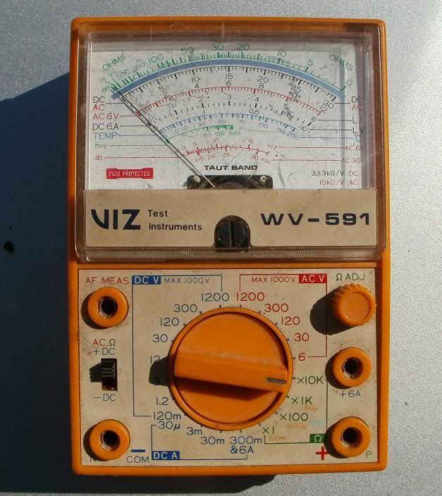
                              Scott's comments about his fancy gauge got me to thinking about all of the tools and such I got from my coworker's father's garage stash I acquired, and I remembered a VOM there. I think it also has the ability to read AC Hz, but I don't have a manual, can't find one on the "NET", so I took a photo of it, hopefully someone can figure it out and tell me how, which lead connections to use, etc. to possibly get the AC Hz readings we are looking for! BTW I put new batteries in the meter, AA and 9 volt, it has a built in protection fuse!


                              T.C.
                              T. C. Gresham
                              81SH "Godzilla" . . .1179cc super-rat.
                              79SF "The Teacher" . . .basket case!
                              History shows again and again,
                              How nature points out the folly of men!

                              Comment


                              • #45
                                Okay, more feedback, I went ahead and tried it.

                                First I put it on the 30V AC scale, and had the (+) lead plugged into the lower right socket, and tested the readout, and it gave me ~7 Vac, top end of the specs!

                                I then put the test lead into the upper right socket...AF which I am assuming means AC Frequency? The needle moved to the 21 position on the bottom db scale in the 30V AC range. I tried revving it and holding it to 4k engine/OEM tach indicated rpm, but the Viz gauge needle barely moved!?

                                I switched the setting to 6Vac, and the needle pegged all the way to the right side, bouncing but essentially stayed pegged!?

                                I don't even know if I'm reading the frequency scale by the bottom red scale or not? There is a GREEN scale and it's marked in the legend HfE, so not sure if that's the AC Hz scale...but it only goes to 500, but is more sensitive in the 0-50 range, which would make sense for analyzing house currents of 50-60hz??

                                If that's the real Hz scale, my problem is what scale to set the rotary switch to....but I'm thinking the 30VAC was correct, and with the needle on the bottom scale ~21 position, that would be between the 30 and 40 hz green scale!?!?

                                T.C.
                                T. C. Gresham
                                81SH "Godzilla" . . .1179cc super-rat.
                                79SF "The Teacher" . . .basket case!
                                History shows again and again,
                                How nature points out the folly of men!

                                Comment

                                Working...
                                X