Announcement

Collapse
No announcement yet.

Godzilla Resurrection: Re-build thread

Collapse
X
 
  • Filter
  • Time
  • Show
Clear All
new posts

  • #46
    Avoid the Extreme High Humid Days.....

    Originally posted by TopCatGr58 View Post
    I'm concerned about trying to put on the actual COLOR layers on the tank in this heat/humidity!
    TC.
    Progress on your project is impressive. Can't wait to see it at XSSE!

    Although I am certainly NO EXPERT, I do a bit of "BackYard Painting". The experts I know, and gain advice and direction from, highly recommend avoiding application in extreme high humidity for those of us working in the BackYard and depend on mother nature to provide the drying heat.

    The humidity will effect the drying time which is not a big deal but it will also effect the GLOSS of the finish coat. I've never been told a humidity number to stay below and now I'm interested in finding that number.... I'll call my buddy at the PPG store and see what he says.

    Respectfully,
    KURT
    Kurt Boehringer
    Peachtree City, Georgia

    1970 - CT70K0 - Mini-Trail
    1978 - SR500 - Thumper
    1979 - CT70H - Mini-Trail
    1979 - XS1100SF - Pensacola
    1980 - XS850SG - Rocky
    1980 - XS1100SG - The Ugly Duck
    1980 - XS1100SG - Mayberry Duck
    1981 - XS1100SH - DEAD Duck Cafe'
    1981 - XJ550 Maxim - Nancy's Mini-Max
    1982 - XJ650 SECA - Hurricane
    1986 - FJ1200 - Georgia Big Red
    1992 - FZR1000 - Genesis
    2016 - FJR1300A - Montgomery

    Comment


    • #47
      Why cant one have a drying "oven"???Would it not hasten curing times? Relying on Mother Nature is inexpensive but is more costly in time ...JAT
      1980 XS650G Special-Two
      1993 Honda ST1100

      Comment


      • #48
        Originally posted by madmax-im View Post
        more costly in time ...JAT
        Not quite! Tens of thousands of dollars for a temperature controlled KILN with proper ventilation, filtration, humidity control, wash down, local & federal permits, etc. A production collision shop can afford one, not too many do-it-yourselfers are going to spring those tens of thousands of dollars for our hobby work.
        Kurt Boehringer
        Peachtree City, Georgia

        1970 - CT70K0 - Mini-Trail
        1978 - SR500 - Thumper
        1979 - CT70H - Mini-Trail
        1979 - XS1100SF - Pensacola
        1980 - XS850SG - Rocky
        1980 - XS1100SG - The Ugly Duck
        1980 - XS1100SG - Mayberry Duck
        1981 - XS1100SH - DEAD Duck Cafe'
        1981 - XJ550 Maxim - Nancy's Mini-Max
        1982 - XJ650 SECA - Hurricane
        1986 - FJ1200 - Georgia Big Red
        1992 - FZR1000 - Genesis
        2016 - FJR1300A - Montgomery

        Comment


        • #49
          Good point ...but there has to be something on a smaller scale that would work at home...i'm ignorant when it comes to paints...but i would think all you would need is a box that gets to 100° should that not suffice...? Something a little less than industrial scale?
          1980 XS650G Special-Two
          1993 Honda ST1100

          Comment


          • #50
            Option

            ...Maybe an explosion in SWMBO's oven?
            -Mike
            _________
            '79 XS1100SF 20k miles
            '80 XS1100SG 44k miles
            '81 XS1100H Venturer 35k miles
            '79 XS750SF 17k miles
            '85 Honda V65 Magna ~7k miles
            '84 Honda V65 Magna 48k miles (parts bike)
            '86 Yamaha VMAX 9k miles

            Previous: '68 Motoguzzi 600cc + '79 XS750SF 22k miles +'84 Honda V65

            Comment


            • #51
              Originally posted by kboehringer View Post
              TC.
              Progress on your project is impressive. Can't wait to see it at XSSE!

              Although I am certainly NO EXPERT, I do a bit of "BackYard Painting". The experts I know, and gain advice and direction from, highly recommend avoiding application in extreme high humidity for those of us working in the BackYard and depend on mother nature to provide the drying heat.

              The humidity will effect the drying time which is not a big deal but it will also effect the GLOSS of the finish coat. I've never been told a humidity number to stay below and now I'm interested in finding that number.... I'll call my buddy at the PPG store and see what he says.

              Respectfully,
              KURT
              Hi Kurt,
              Our painter at work was once over ruled by the production manager and told to paint on a humid day 
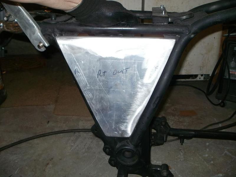
The three days of sanding that followed is not mentioned...but the painter has the final say now
              Phil
              1981 XS1100 H Venturer ( Addie)
              1983 XJ 650 Maxim
              2004 Kawasaki Concours. ( Black Bear)

              Comment


              • #52
                Home Despot sells aluminum faced foam boards, which can be cut with a razor knife, taped together with duct tape, and makes a ersatz curing oven. (The tape should be applied on the out side, to keep the heat from softening its adhesive.)
                An open topped box, big enough to cover all the pieces, placed open side down on a base of foam sheet, with a hole the size of a hair dryer cut near the open side of the box, (which becomes the bottom edge when placed over the parts), and another hole the same size cut near the bottom of the box on the same side as the top hole, becomes your curing oven.
                Commercial curing/spray booths will run temperatures up to 140 deg F.
                A cooking thermometer poked through the foam near the bottom hole, (the outlet), will let you adjust the hair dryer to attain the proper temperature.
                Don't worry about the EPA. You will not generate enough VOCs to warrant their attention.
                One caveat. I would make sure that the airflow from the dryer doesn't impinge directly on any of the pieces. A baffle inside could work, or blow the air into a corner at the top of the cover box. Some cheese cloth over the inlet of the dryer would keep errant bugs and dust out, but the paint should have already flashed off by the time you get all the pieces placed and the top on, so any lint should wipe off after curing.

                No huffing!

                CZ

                Comment


                • #53
                  If it's not one thing, it's another!

                  Hey Kurt,

                  You're not a very good liar!! I wish I was making progress over the last few weeks, but I feel like I have been spinning my wheels! BUT...Today the weather turned tolerable with temps in the upper 80's, low 90's, and less humidity, AND I have been able to take a few extra days off now, so I'll have 4 good days to try to really get some stuff done!!!

                  Okay, proceeded to work on my petcock adapter plates...had lots of spare aluminum plate, had already drilled the main hole and mounting holes, and had roughed out the shape/size, but had to eventually go to Northern Tool to find a drill bit big enough(my set stops at 1/2") to make the preliminary hole so that I could run my 3/8" NPT tap for the petcocks! It is supposed to be a 37/64", but I settled on a 9/16"=36/64 but was enough room to start the tap working!!!

                  Got the first one tapped mounted in my little 3-1/2" Sears Vice I've had for decades, but while working on the second one, the base lock wouldn't hold tight, and when I finally took a closer look, saw this!


                  Here's the bottom view showing it's a complete thru and thru crack. The locking bolt head was also messed up, this is a new one just test fitting.


                  So..I took it apart and off of my bench, drill/wire brushed the excess paint off of the edges, and proceeded to do what folks have said you can't/shouldn't do....WELD CAST IRON!


                  Put it together, finished doing the tap on the 2nd petcock.

                  Here are the petcocks temporarily mounted into the adapter plates. YES, I KNOW, they are different, got one years ago from a fellow Xsive that got it from PNM, and then got the other one from eBay recently!

                  And here they are after giving them a bit of a shining...nice HF buffer!!


                  SO..then I proceeded on to modding the grab rail. Cut off the ends, fashioned the slotted, thinned ends for the shock bolt mount. Prior to that I realized that the ends were just a bit too wide, so I put it in my newly repaired vice, set the heat gun on 1000 degree high setting, and softened it up a bit so that I could just bend the bar a little inwards. Got one side bent, then proceeded to work on the other end....and then THIS HAPPENED!


                  So...I again cleaned up the edges, and got out the wire feeder and went after it!!!


                  We'll see how long it lasts. 
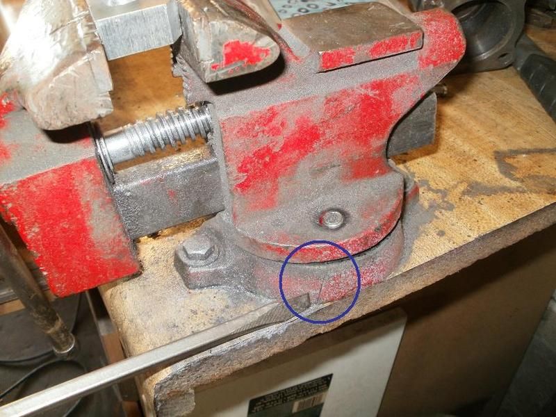
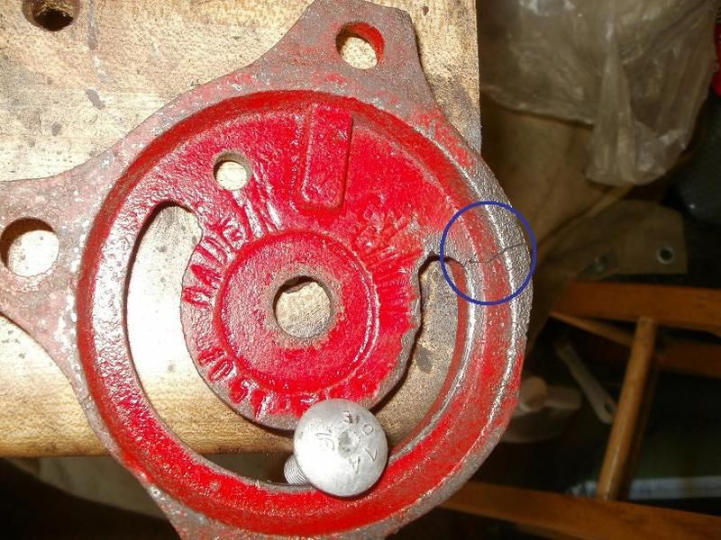
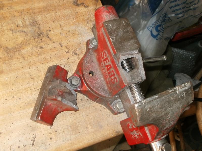
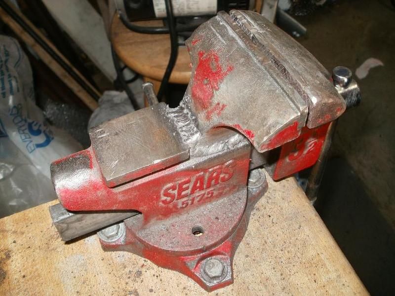
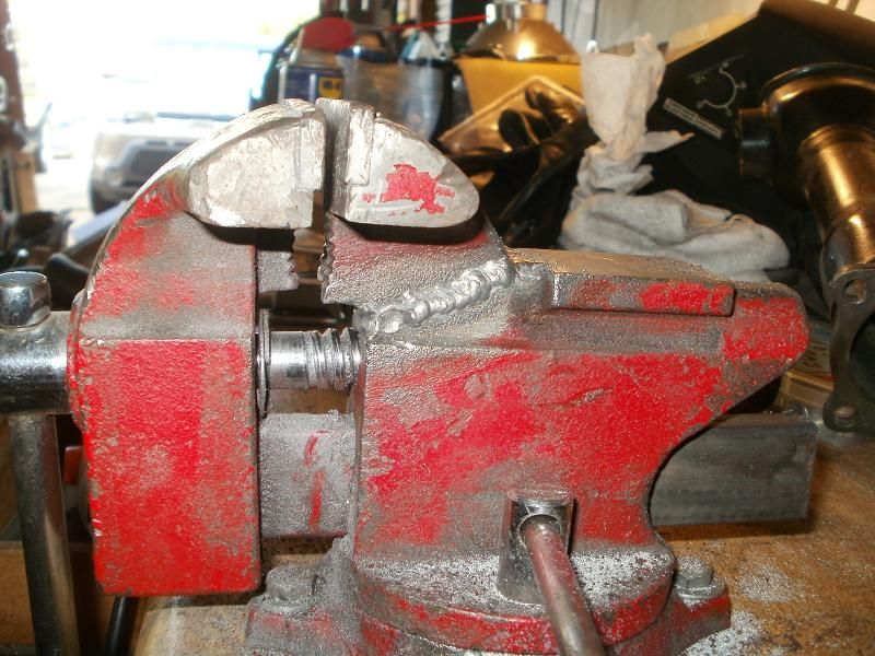
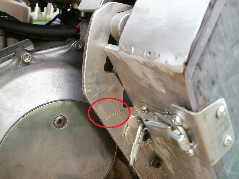
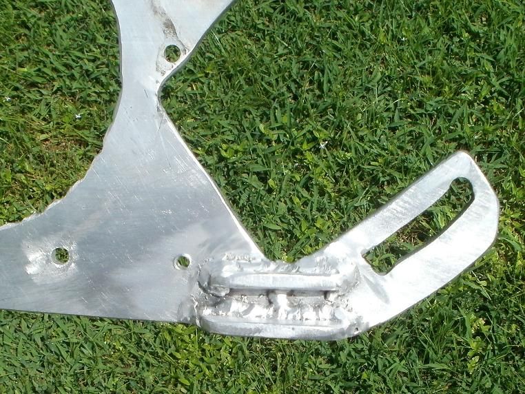
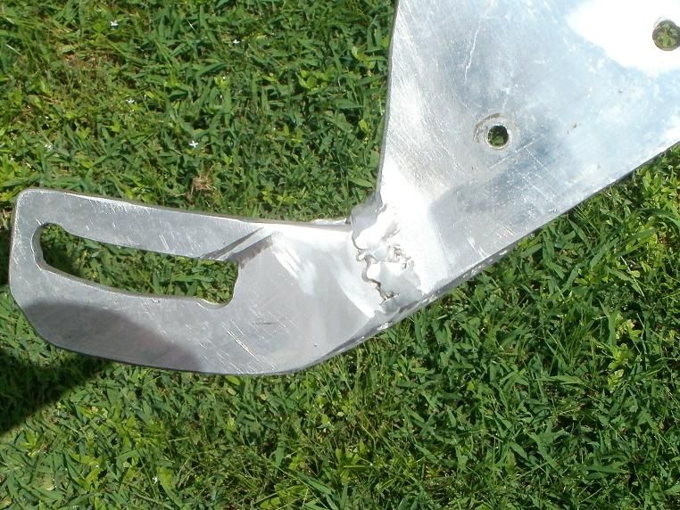
I have a spare one from my B-I-L's stuff if this one breaks again!

                  Finally, just a few views of my plans to adapt the fender. This first one shows that I have enlarged the forward mounting hole and moved the fender forward to that location. I'll be cutting off the ugly turn signal stalk section, and have already slightly narrowed the fender front a bit to fit between the rails so it'll tilt down more in the front edge to better mate with the plastic inner fender/splash guard.


                  This shows the partially modded grab rail with the seat...I KNOW, it's not at the right angle YET...I'll be modding the frame rails a little more to allow room to drop the mounts of the grab rail downwards so that they will fit into the lower existing tang/hole! I don't trust myself with trying to mod/cut/weld the ALUMINUM rail mounting tangs....I'm much better at welding/modding the STEEL!! I didn't show it, but I also got the weld nuts mounted on the gas tank tail mount area, drilled the tank mount holes to hold the 1/4" nylon insert/bushings that the knurled finger bolts will be securing it with. I'll be laying a layer of rubber cushion between the tank and mounting bracket as well. Also got the spring seat adapter/mounting pan painted so I can finally attach it to the actual SEAT tomorrow!! Baby Steps...but I gotta grow up fast, only 5 more weekends till XSSE!!!!

                  T.C.
                  T. C. Gresham
                  81SH "Godzilla" . . .1179cc super-rat.
                  79SF "The Teacher" . . .basket case!
                  History shows again and again,
                  How nature points out the folly of men!

                  Comment


                  • #54
                    T.C., in reference to vice 'fix', it is cast steel, not cast iron.

                    BTW, if it WERE cast iron, use of an carc welder using welding rod for cast iron would of been the fix. The problem welding(arc or otherwise) cast iron is only one inch of weld can be done, then item being repaired HAS to completely cool before continuing another inch, so on and so on. BTDT, and it IS time consuming till finished!
                    81H Venturer1100 "The Bentley" (on steroids) 97 Yamaha YZ250(age reducer) 92 Honda ST1100 "Twisty"(touring rocket) Age is relative to the number of seconds counted 'airing' out an 85ft. table-top.

                    Comment


                    • #55
                      T. C.-- I don't know why, but the pictures and narrative re: your vice struck me as a bit entertaining and sort of chuckle worthy. I must say, you are a skilled welder and have good old American ingenuity, so, definitely, kudos to you for your craftsmanship and work. Here's to 30 more years of the red vice's life! Keep up the good work!
                      79 F
                      Previously owned: (among others)
                      1969 Harley- Davidson Rapido 125 (Aermacchi)
                      1967 Suzuki X6 Hustler
                      1973 Suzuki TM 125
                      1979 XS1100 F
                      2005 Kaw. Vulcan VN800
                      1991 BMW K75

                      Comment


                      • #56
                        The Best Laid Plans of Mice and Men

                        Hey folks,

                        Well, Mark, glad you have a sense of humor, I was trying to be funny as well as informative!

                        Okay, attacked the grab rail project today. Below shows the tail rails that were just bit too wide for the grab rail mounts to fit past, drop down to the lower mounting bracket/hole. I had done what I thought were some proper measurements, considering angle of rail after cutting off ends, etc. and thought I had it right. SO..I went about narrowing the position of the mounting holes...by cutting thru the rails vertically, made two passes with the cutting disc to allow enough room so when I cut off the outer sections and then rewelded them back into place, they would be narrower and allow the fairly non flexible OEM grab rail mounting points to drop down into place.


                        Here's the tail pieces narrowed, and the grab rail mounts slid down past just fine.
                        And I had already cut off the grab rail shock mount ends, recut and fashioned them with the metal cutting bandsaw and drill press, grinder, etc.!


                        BUT apparently my measurements weren't as precise as I thought!
                        Several hours of fabrication down the drain!!!


                        SO...I realized I was going to have to bite the bullet and do some ALUMINUM Welding afterall! I don't have a fancy AC TIG unit like I think Kurt has to make those nice clean welds. I had previously had some problems last year at the end of making my gauge cluster box, had the wire birdsnest and just get stuck in the liner, replaced the liner this year. I still had plenty of the stiffer 5350?? Aluminum MIG wire and some 100% argon gas, connected the gas, reversed the polarity of my wire feeder for MIG running, and apprehensively fed the aluminum wire into the handle, changed the nozzle to MIG Gas Shield CONE and larger wire feeder tip for the slightly larger wire and it's tendency to expand while heating!

                        I had the OEM ends of the grab rail left over, and figured out the right angle and length to cut both the remaining grab rail, and the OEM shaped shock ends. I then used my angle grinder and cut some nice 45 degree cutouts on the outer edges ends of all pieces to be welded, and ground away all of the surface to expose raw non-oxidized aluminum skin. I then positioned the rail and shock ends, and did some preliminary tack welds with the lowest "A" power setting. I then took it off of the bike and put it in my VICE , and proceeded to try to weld it. I had used the lowest power on the thin 1/8" thick plate material, but I realized I wasn't getting any real penetration! I then tried the "B" setting, a little better, but still not deep enough. I then set it to the "C" setting, and VIOLA, had the level of penetration and melting that I wanted. I then ground away the previous tacked sections as well as the other poor surface burns, and then laid down some nice deep beads all around the joints!

                        I then used the grinder for what it's for....smoothing out the lumpy thicker remaining beads. I also realized that I would have a better angle for the shock mount ends if I reversed/flipped them outer edge inward. But this left the outside of the rest of the grab rail with the grooved center stripe stopping prematurely! SO....again I used my bandsaw to remove most of the extra surface aluminum down almost to the surface level of the center stripe, and then used the grinder to smooth out the surface down to plain flat aluminum.


                        SO.....I think it looks okay, and as you can see, I got the position and distance from the seat to where I think it should be..allowing enough of a gap for the spring seat to move up and down without hitting the rail!

                        I also modded the OEM seat mounts to be able to bolt the OEM grab rail mounts to them! This angle allows you to see the inverted shock mount sections that will fit up against the NEW shock mount eyelets.


                        T.C.
                        T. C. Gresham
                        81SH "Godzilla" . . .1179cc super-rat.
                        79SF "The Teacher" . . .basket case!
                        History shows again and again,
                        How nature points out the folly of men!

                        Comment


                        • #57
                          The Saga Continues....

                          Hey again,

                          Okay, since I already had the welder set up for MIG Aluminum welding, I decided to tackle the sidecovers as part of getting the frame ready to accept the transplants! However, because of concern about having to mod the battery holder and fuseblock plate location too much, I decided to go with more than flat plates mounted BETWEEN the frame rails. I had ordered a couple of 12" x 12" square 1/4" thick aluminum plates just for this purpose. I probably could have done it with 3/16' or even 1/8" thick plate, but wanted it to be substantial in strength, and thicker actually would make it a bit easier to weld, more room for more forgiveness of mistakes!

                          SO...I got out the cardboard, mocked up the shape, then transferred that to the plate, used the metal cutting bandsaw to cut them out. Then after ensuring that they were the correct shape for the opening, I then checked and saw how the frame rails bend inwards a few inches up from the swingarm joint, as well as the top rail just under the seat. SO...I figured out how to add a couple of extra top and front side pieces to allow a contour fit to those rails. and this will also allow the sidecovers to sit outwards a little bit away from the frame/battery in hopes of having enough room for at least MINIMAL modding of the battery case/fuseblock. The TCI will be going where the OEM tool box used to be! This will also help the bike not to look too skinny in that area.

                          I welded the pieces on the inside first...wasn't worried about how pretty they were, just wanted some strength holding them together. THEN I ran beads along the seams on the outside. After the grab rail experience, I knew to use the "C" power setting, feeder at maximum speed, scrubbed the edges to ensure fresh raw unoxidized surfaces, and went after it. Then was able to use the grinder with a 80grit flap disc to smooth out the outer beads and edges. I think they look pretty good, will be painting them eventually!

                          So...now for the requisite photo documentation. That aluminum dust gets everywhere!


                          In these photos, you can also see the welded nuts on top of the fuel tank support rail.


                          Okay, that's all for today! While I've got the welder rigged for Aluminum I'll be removing the ALT cover, ALT, and it's mounting bracket and welding it where it got stress cracked from it's vibration. I'll also weld an extra support rail on the inside edge to help further strengthen the bracket/plate to help prevent a repeat fracture. I'll be fixing the vibration problem....have to center the drive pulley a bit better on the crankshaft....it's just a little off, thought the belt would make it okay, but the pulsing pulling apparently was too much for the bracket.

                          Here's the photo of that I posted several pages/weeks ago.


                          T.C.

                          Hey Kurt, hope you aren't mad at me for what I said, I showed a Winky Smiley trying to indicate that it was a jest/joke!? Perhaps you're just real busy with Bennie/MadMaxim finishing the paint and reassembly work!?
                          T. C. Gresham
                          81SH "Godzilla" . . .1179cc super-rat.
                          79SF "The Teacher" . . .basket case!
                          History shows again and again,
                          How nature points out the folly of men!

                          Comment


                          • #58
                            Day 4 of the surge.

                            Hey again,

                            Well, the heat and humidity came back a bit today, but I forged onward. I took off the bandsaw blade bracket/guide that had broken a while back, cleaned up the edges and then welded it back together...it also was aluminum. Yes, I know the beads are prominent, but since it broke before, I felt more bead would possibly provide a bit more support, and it's appearance wasn't important as long as the part fit back on the bandsaw and worked like it was supposed to.


                            Then, I took the Mini Race Alt cover, Alt itself, and finally the mounting bracket off. Cleaned up it's edges, surfaces for a few inches beyond the crack, and then first welded up the crack on both sides, and then fashioned a couple of little extra support brackets/gussets that I position across the crack and welded in place. They will be towards the engine, away from direct view so their aesthetics won't be a problem.


                            And I also took the rotor and pulley and mounting plate off, separated the pulley/plate from the rotor, and then chucked it in my Lathe so I could get my dial indicator on it to get it centered first. THEN I check the centricity of the pulley, and it was about 30 thousands out of round/position from center. Not much, but at 7K+ rpm it apparently is enough to set up a harmonic vibration that cracked that bracket. I was able to just rotate the pulley within the plate...there are 3 mounting holes and I just lined up the next position of holes, and rechecked it and it was down to ~15 thousandths, hopefully that will be enough along with the reinforced bracket to prevent it from causing any more vibration problems!?

                            Here's a photo from the Mini Race Alt thread just showing the pulley and mounting plate on the rotor with the pulley and ALT mounted on the bracket!


                            T.C.
                            T. C. Gresham
                            81SH "Godzilla" . . .1179cc super-rat.
                            79SF "The Teacher" . . .basket case!
                            History shows again and again,
                            How nature points out the folly of men!

                            Comment


                            • #59
                              Hey TC,
                              Aluminum has a finite life when exposed to any stresses, and unless you have the back, (inside) , end of the alternator fixed so that it cannot move, there are going to be bending stresses on the aluminum plate. Not a lot, but they all add up to the failure point of aluminum.
                              Every time the belt gets tight, it tries to pull the pulleys together, which tries to bend the plate. If you could fasten the back end of the alternator to the top two bolts of the clutch cover, that might help. Some sort of a bracket made out of 16 gauge steel, perhaps? I don't know if there is anything on the back of the alternator to attach to, but anything would help. Even a saddle with rubber lining and a clamp around the alternator. Any thing to dampen the vibration.

                              Just a thought, pro bono.

                              CZ

                              Comment


                              • #60
                                Side covers are spectacular!

                                Originally posted by TopCatGr58 View Post
                                I think they look pretty good, will be painting them eventually!
                                SNIP..
                                Hey Kurt, hope you aren't mad at me? NO, NOT AT ALL! Just got back from FL with my whole clan and still a little work to do on those other projects.
                                T.C.
                                Those side covers look better than good....They are exceptional! Have you considered POLISHING them? Maybe just the top or the just the edges or vice-versa with the paint? Kinda nice to show off that Aluminum work in some way?

                                I wonder a bit about those seat springs? You may have to adjust that a little. I use the same seat on my Dead Duck and it is EXTREMELY comfortable and makes for a feel on the XS11 like you have some "Grip" on the bike. The elevated rear may keep you from sitting in the sweet spot of that seat even once you have your weight on it... You'll be able to judge once the assembly is complete and you can sit on the bike.

                                I've got only a handful of items to complete on my bikes before XSSE but at the speed your working you'll be done before me...

                                Kurt
                                Kurt Boehringer
                                Peachtree City, Georgia

                                1970 - CT70K0 - Mini-Trail
                                1978 - SR500 - Thumper
                                1979 - CT70H - Mini-Trail
                                1979 - XS1100SF - Pensacola
                                1980 - XS850SG - Rocky
                                1980 - XS1100SG - The Ugly Duck
                                1980 - XS1100SG - Mayberry Duck
                                1981 - XS1100SH - DEAD Duck Cafe'
                                1981 - XJ550 Maxim - Nancy's Mini-Max
                                1982 - XJ650 SECA - Hurricane
                                1986 - FJ1200 - Georgia Big Red
                                1992 - FZR1000 - Genesis
                                2016 - FJR1300A - Montgomery

                                Comment

                                Working...
                                X