Announcement

Collapse
No announcement yet.

Alternative Alternator Options

Collapse
X
 
  • Filter
  • Time
  • Show
Clear All
new posts

  • TC, if I'm reading the above right, you're basically depending on friction between the rotor/spacer and spacer/pulley to stabilise the pulley. While that would help some, I think long-term you'd still have the same problem. But you're on the right track.

    If it were me, I'd try this:

    [IMG][/IMG]
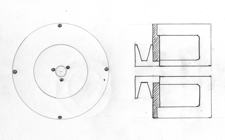
    Now, this isn't in anything close to scale, just a quick scribble.

    Machine your 'spacer' (the shaded part) so it fits partially into the rotor; a light interference fit would be good. Take the pulley, and machine the long hub to a uniform size. Bore the spacer the same size or a few thou under, press the pulley into the spacer. Now your pulley is located wholely by the spacer/rotor; the bolt is now simply retaining it. I think if you assembled this with red locktite on the pulley hub and at the rotor/spacer joint, that may take care of the set screw, but if not, you could put some small (say, 10-24) screws into the edge of the rotor and through the pulley to take care of the shear forces. If you spaced these equally, that would eliminate any balance problems. This also shortens the pulley and bolt, giving a slightly less wide assembly.

    Admittedly, this is no longer doable in your garage with a rock and a stick, but the required machining is simple (i.e. reasonably cheap) and wouldn't add a huge $ outlay to the total. The drilling/tapping for the screws could be done at home, so you really only need the spacer/pulley machined. You may be able to find a pulley that already has the right type hub, so now all you need is the spacer...
    Last edited by crazy steve; 03-12-2011, 01:43 AM.
    Fast, Cheap, Reliable... Pick any two

    '78E original owner - resto project
    '78E ???? owner - Modder project FJ forks, 4-piston calipers F/R, 160/80-16 rear tire
    '82 XJ rebuild project
    '80SG restified, red SOLD
    '79F parts...
    '81H more parts...

    Other current bikes:
    '93 XL1200 Anniversary Sportster 85RWHP
    '86 XL883/1200 Chopper
    '82 XL1000 w/1450cc Buell, Baker 6-speed, in-progress project
    Cage: '13 Mustang GT/CS with a few 'custom' touches
    Yep, can't leave nuthin' alone...

    Comment


    • Hey Steve,

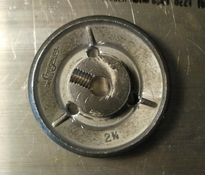
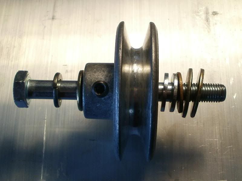
      Thanks for that diagram/explanation. Here's the other photo of the pulley:


      You're saying that I/we don't really have to worry about the set screw in the hub of the pulley since it's the plate and bolt that will be providing the friction/grip to keep it from spinning loose, along with the possible addition of other screws into the pulley/plate.

      So...this protruding end could provide the material needed to go into the plate, it's already mostly cast/molded quite round, and after removing the set screw, then would just require a little machining down so it just makes contact with the rotor central hub, and is flush with the fixation plate.

      This still leaves "some" machining to be done to the actual rotor plate, unless I use a large washer to fill the little void elevation difference between the rotor central hub and outer ring. I'll have to measure the pulley protruding hub's diameter, perhaps a DRILL bit of similar size could be found to make the hole in the plate that the pulley hub could be interference fitted into, avoiding any actual mill/lathe type machining!?

      I do like the idea of the pulley to plate set screws, around the hub moreso than in the belt track groove, being able to tap some threads into the plate should be relatively easy to do, being then able to use ie. some 6mm socket hex head bolts, with locktite and such!

      T.C.
      T. C. Gresham
      81SH "Godzilla" . . .1179cc super-rat.
      79SF "The Teacher" . . .basket case!
      History shows again and again,
      How nature points out the folly of men!

      Comment


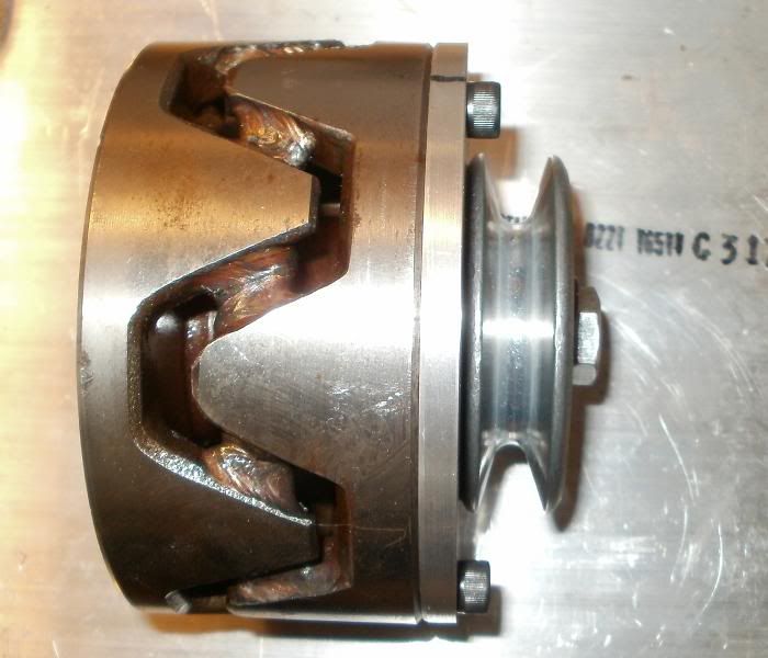
      • Okay, I just went out and did some quick measurements.

        The diameter of the central rotor hub is ~ 1.75" wide, the width of the pulley hub is ~1.15" wide, the depth of the pulley hub is 0.62", but there's very little height/elevation difference between the rotor's hub and outer ring, barely 1mm or less(~0.04"). ALSO the pulley is about 0.07" beyond the Rotor's outer ring surface, it's almost flush with the rotor surface.

        With the use of a 1/4" plate, I/we would still need to remove some 0.37" worth off of the protruding portion of the pulley hub. With the use of the plate, it would actually cause the pulley to protrude outward away from the engine/rotor more than it is now. The washer group in the earlier photo was just to take up the recess void and allow the pulley to be just above the surface plane of the outer rotor ring. I don't actually want/need the pulley any closer to the engine head because the ALT's position on the plate just clears the carbs, heads.

        The pulley hub is slightly tapered! Yeah, I could machine it to a truer cylinder but that's again adding a machining step! A slower way of making the PLATE interference hole would be to use a slightly narrower drill bit, and then either a dremmel stone or round/curved file to make the slight taper contour for the pulley hub...again trying to avoid fancy machine tools.

        T.C.
        T. C. Gresham
        81SH "Godzilla" . . .1179cc super-rat.
        79SF "The Teacher" . . .basket case!
        History shows again and again,
        How nature points out the folly of men!

        Comment


        • I'll tell you that using just locktite as the means to prevent pulley slip wouldn't be my first choice, I just threw that out there as a possibility. I'd use the screws to be absolutely sure. Looking at your pic of the pulley, there's enough room to do this without issues.

          The main thing going on here is you're making the centering/location of the pulley independent of the bolt. Any sideways movement is limited by the rotor/spacer, not the bolt if the 'fit' is tight enough, and that's why machining this for a press/interference fit is important. Now, 'pinning' the pulley/spacer with small screws could allow you to be a bit sloppy with fit but that would put the sideways stress on those instead.

          If you really want to eliminate as much 'machining' as possible, this is what I'd do; do a press-fit between the pully and the spacer. This wouldn't be that hard, although I'd still put 3-4 small screws bolting the pulley/pacer together.
          You could do the pressing with a couple of sockets and a vice if need be. At the spacer/rotor surface, if you don't want to recess the spacer then up the number of screws to 6 or 8 fastening the spacer to the rotor.

          There's multiple ways to do this; if 1/4" aluminum is too thick for the spacer, use something thinner. Although below 3/16" I'd switch to steel for this, and maybe a steel pulley if you can find one; you could weld the pulley to the spacer. Just don't make that poor 10mm bolt do double-duty...
          Fast, Cheap, Reliable... Pick any two

          '78E original owner - resto project
          '78E ???? owner - Modder project FJ forks, 4-piston calipers F/R, 160/80-16 rear tire
          '82 XJ rebuild project
          '80SG restified, red SOLD
          '79F parts...
          '81H more parts...

          Other current bikes:
          '93 XL1200 Anniversary Sportster 85RWHP
          '86 XL883/1200 Chopper
          '82 XL1000 w/1450cc Buell, Baker 6-speed, in-progress project
          Cage: '13 Mustang GT/CS with a few 'custom' touches
          Yep, can't leave nuthin' alone...

          Comment


          • Here's what I've done so far!

            Hey Steve,

            Well, I made it a modestly snug fit, not enough to require a PRESS type fit, but it's SNUG, no wobble space! I cheated and used my lathe because I didn't have either a large enough drill bit, or even one of those door handle hole drill/saw type bits...which I think would also work for folks to get the center hole close to the 1.125" diameter needed for the pulley hub.

            SO...are you saying that aside from putting in 3 securing bolts thru the pulley to the plate, that I need to somehow SECURE the plate by Drilling holes in it's perimeter and INTO the ROTOR surface, then tap the ROTOR holes, and then bolt the plate to the ROTOR!?!? Geez....isn't this a bit OVER Engineering the thing!?

            Okay, heres the photos, I know we all love photos!

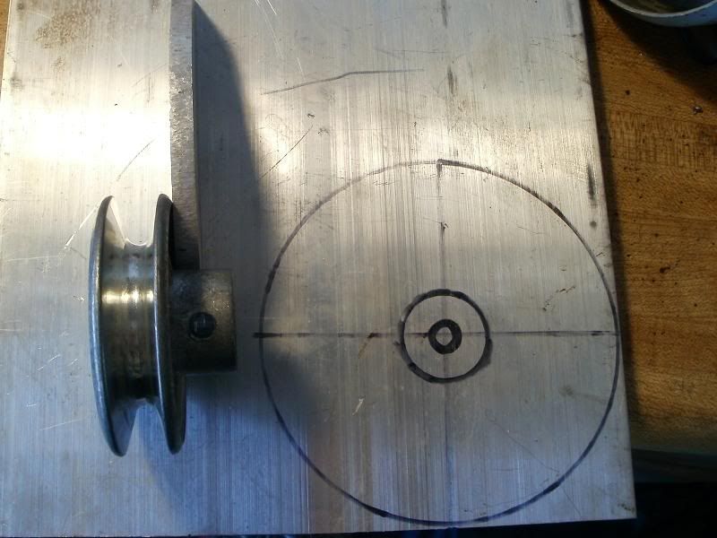
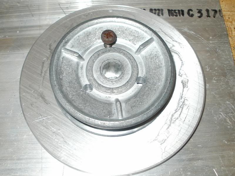
            This shows the pulley hub and how far it would stick out thru the 1/4" plate, provides a guide to cutting of part of the hub, and the extra piece of 8" x 8" plate I had to make the round pulley/rotor spacer plate.


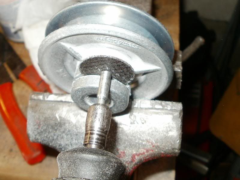
            Using a Dremmel with an oversized cut off fiber disc!


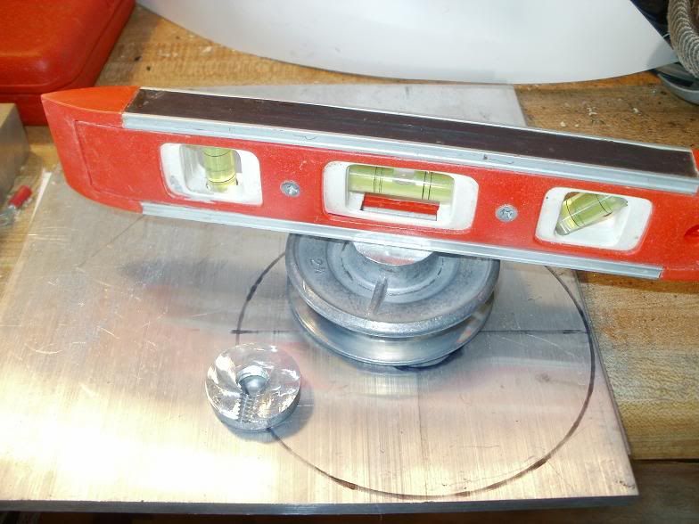
            Once you get a LEVEL surface, then you can use a level on the cut off edge along with a large flat file to get it FLAT!


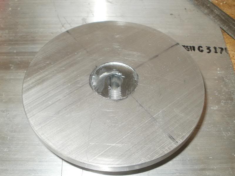
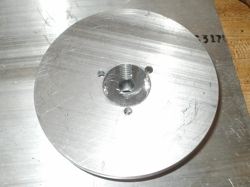
            Here's the plate with the center hole bored into it for the hub, already cut off, but I think I may have cut a little too much, there's a slight recess between the pulley hub and the plate. I should have made the center hole, pushed the pulley thru, and used the plate as a guide!


            I spaced the holes between the ribs, and in the outer groove to allow room for the center bolt/washer. Once I drilled the first hole with the ~3/16" bit, I put a tight screw into the pulley/plate hole to keep them from slipping/spinning while I drilled the other 2 holes.


            This just shows how close to the edge of the plate center hole the 3 pulley holes ended up!


            Surprisingly, the 3 holes came out right in the middle of the ribs on the hub side!


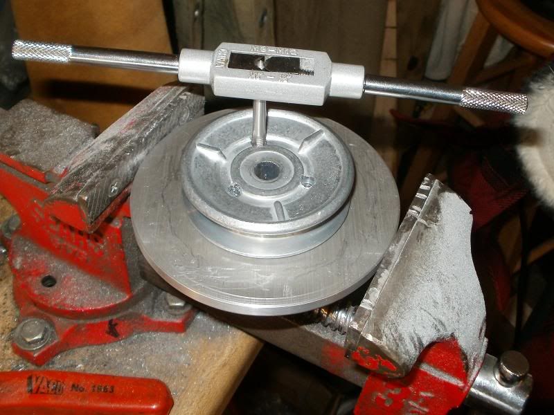
            I then drilled 1/4" holes just into the pulley for the 6mm bolts, then positioned the pulley to help guide the TAP for the 6mm x 1.00 threads!


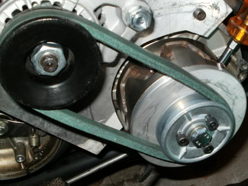
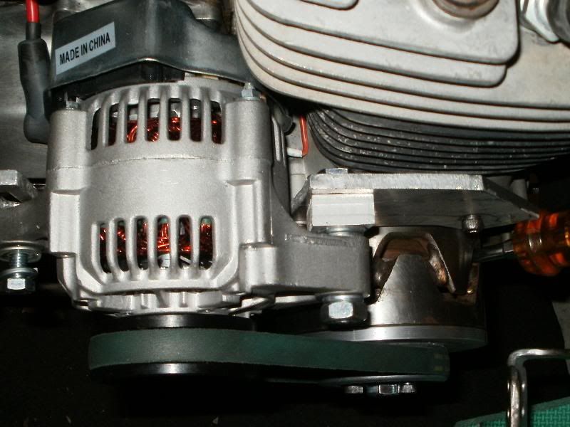
            This one is a little out of focus, just shows the mounting of the spacer plate, I had to get a SHORTER 75mm long 10mm bolt, the 100mm was too long after whacking off the hub portion. The 3 pulley to plate bolts are sticking out a little, they are 25mm long, will need to tighten then down with locktite, and then cut off the protruding ~2-3mms off of the other plate side since they would hit the ROTOR center hub.


            The drive pulley is just a few mm's more outward from the engine than before, so I'll need to add some more washers, or make a thicker spacer for the ALT's base mount hole! This was just a trial fitting!

            I'm thinking that ROTOR is STEEL more than cast iron, but not sure??

            I guess I can drill and tap some holes into it to secure the plate to keep the stress off of the center 10mm bolt??? WOULD 3 be enough, or 4??

            T.C.
            T. C. Gresham
            81SH "Godzilla" . . .1179cc super-rat.
            79SF "The Teacher" . . .basket case!
            History shows again and again,
            How nature points out the folly of men!

            Comment


            • Originally posted by TopCatGr58 View Post
              I guess I can drill and tap some holes into it to secure the plate to keep the stress off of the center 10mm bolt??? WOULD 3 be enough, or 4??
              I think three should be adequate, I just figured four would be easier to evenly space. You want even spacing to maintain balance. I think I would use red locktite on the rotor/spacer joint as added insurance..

              That should do it!
              Last edited by crazy steve; 03-12-2011, 08:04 PM.
              Fast, Cheap, Reliable... Pick any two

              '78E original owner - resto project
              '78E ???? owner - Modder project FJ forks, 4-piston calipers F/R, 160/80-16 rear tire
              '82 XJ rebuild project
              '80SG restified, red SOLD
              '79F parts...
              '81H more parts...

              Other current bikes:
              '93 XL1200 Anniversary Sportster 85RWHP
              '86 XL883/1200 Chopper
              '82 XL1000 w/1450cc Buell, Baker 6-speed, in-progress project
              Cage: '13 Mustang GT/CS with a few 'custom' touches
              Yep, can't leave nuthin' alone...

              Comment


              • I like the way it's shaping up now!
                Nathan
                KD9ARL

                μολὼν λαβέ

                1978 XS1100E
                K&N Filter
                #45 pilot Jet, #137.5 Main Jet
                OEM Exhaust
                ATK Fork Brace
                LED Dash lights
                Ammeter, Oil Pressure, Oil Temp, and Volt Meters

                Green Monster Coils
                SS Brake Lines
                Vision 550 Auto Tensioner

                In any moment of decision the best thing you can do is the right thing, the next best thing is the wrong thing, and the worst thing you can do is nothing.

                Theodore Roosevelt

                Comment


                • Hey TC, have you given any thought to trying a link belt for this application? This might help solve some of the alignment issues.
                  Ken Talbot

                  Comment


                  • Hey Ken,

                    Thanks, but those applications seem to be more for in home applications at speeds of 1700 rpm or less....I don't think lathe and table saw motors spin at 3500 rpm, much less 7000, and at 2.75" diameter pulley size, I've calculated that to about 5-6000 FPS belt movement.

                    Okay, spent most of the afternoon doing more work, aligning parts to drill and such, here are some more photos!

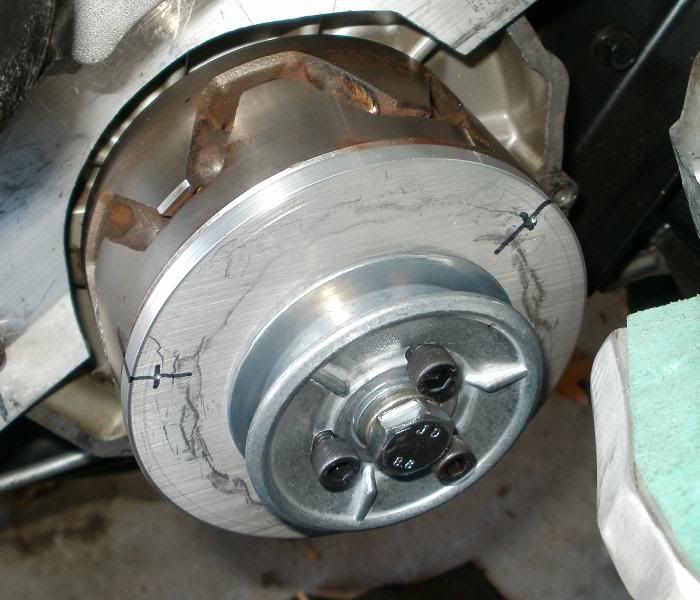
                    First, marked the Rotor every other POLE, since there are 6 poles on each end, then putting 3 bolt holes seemed logical for balance and such! I used a micrometer/caliper to measure the 1/2 depth of the outer rotor ring, then marked, centerpunched, and then HAND drilled the holes thru the aluminum plate while the bolt and such held it securely in place.

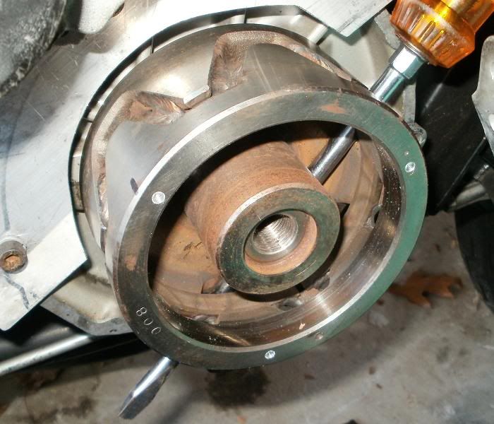
                    I drilled a little into the ROTOR to make "centerpunch" type marks for drilling with the drill press.


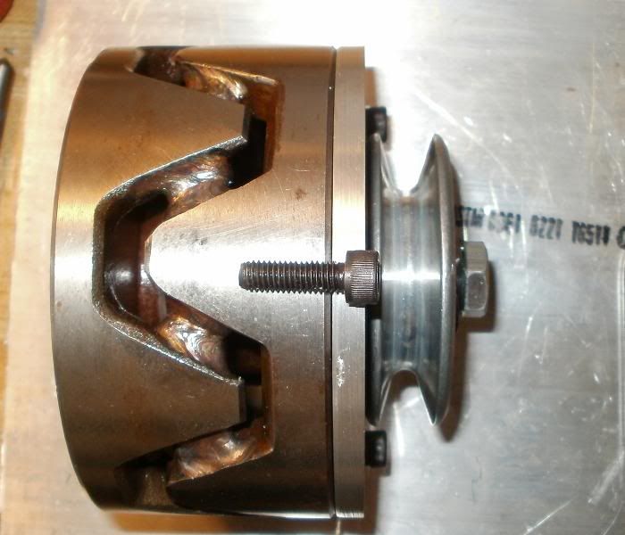
                    Apology for focus, the Rotor with plate, depth markings on side to 1", to allow room for tapered end of 6mm tap since it's not a dead/flat/bottom tap. I had to go buy a tap/die set from LOWES, my cheap Pittsburgh=CHINESE crap tap started to TWIST in the hole! Fortunately I caught it before I sheared it in half! The new set had matching drill bits, and that also contributed in a slightly easier and successful tapping, since the drill bit for the 6mm tap was 13/64" instead of the 3/16=12/64" I had first used! With STEEL, having less material to break as chips goes a long way!
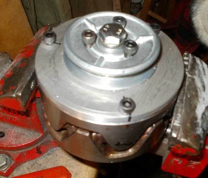
                    Also, instead of trying to cut off the ends of the 3 pulley bolts, I just drilled matching holes into the ROTORs central hub to allow for the bolts to protrude a little, so I could have as much thread grip for the pulley bolts as possible.


                    All of this drilling/tapping has made me realize that this is most likely a one way non-reversible mod! Since the size of the balancing hole drilled in the rotor was so small/shallow, it seems like it will be very easy to THROW OFF the balance with all of the drilling, not to mention having less metal in the POLES for breaking the magnetic fields for electricity generation, and again, the balance issue of the Rotor!?

                    HOUSTON...WE HAVE A PROBLEM!

                    The side of the pulley isn't very thick, and as you can see, the height of the plate bolt sticks out quite far, and will hit the belt!


                    SO....thinking of options here!?


                    1) Countersink the plate holes about 0.12" deep, then also grind off about another 0.06" from the head of the bolt. But this leaves only 0.12" worth of plate material under the bolt head to secure it!?!?

                    2) Use a larger/thick plate....ie. 5/16", can allow a deeper countersink...BTW, would need to use a FLAT tipped End Cutting BORE tip, not a regular drill bit since drill bits are TAPERED on their tips/ends! This would allow a little more plate thickness for strength, but a thicker plate will be more tougher to cut with a jigsaw! Again, trying to keep the costs containable/reasonable, and the rotor plate was the leftover piece from the main 1/4" ALT mount plate, which would now become a 5/16" plate....stronger, but a little more weight as well!

                    3) Cut another 1/4" thick spacer plate to put under the pulley wide enough to provide the leverage against the pulley outer rim for stability, but now the center HUB isn't long/deep enough...so would have to get another pulley and start over, also would take us back to the 100mm long center bolt!? And longer bolts required to secure the pulley against the 1/4" extra spacer plate AND the base plate! It just seems to get better and better!?

                    I'm starting to TIRE of this project now!

                    T.C.
                    T. C. Gresham
                    81SH "Godzilla" . . .1179cc super-rat.
                    79SF "The Teacher" . . .basket case!
                    History shows again and again,
                    How nature points out the folly of men!

                    Comment


                    • hang in there TC ur nearly there,
                      how about using a pin instead of a bolt
                      something similar to whats fitted to the shift fork?
                      if the pulley/plate sits tight up against the rotor a pin or 2
                      should keep it in place without anything protruding.
                      pete


                      new owner of
                      08 gen2 hayabusa


                      former owner
                      1981 xs1100 RH (aus) (5N5)
                      zrx carbs
                      18mm float height
                      145 main jets
                      38 pilots
                      slide needle shimmed .5mm washer
                      fitted with v/stax and uni pod filters

                      [url]http://www.youtube.com/watch?v=3pA8dwxmAVA&feature=mfu_in_order&list=UL[/url]

                      Comment


                      • You could change the cap heads to Socket Button Head Cap Screw. I believe the height would be less and not interferer with the belt.
                        Current 1981 xs1100H
                        First Bike was 1982 xj550j

                        Comment


                        • Originally posted by TopCatGr58 View Post
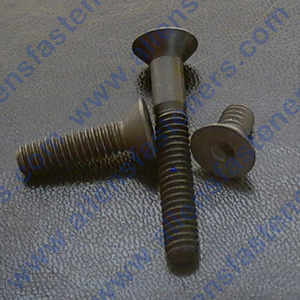
                          Use these instead and countersink them.... http://www.allensfasteners.com/detai...oduct_ID=70388 Put some locktite under the head to retain them.

                          The amount of metal you're removing, and where you're removing it from should have zero effect if you decide to remove all this, with one caveat: each hole should be drilled to exactly the same depth, therefore removing the exact same amount of metal at each point. If you do this, there should be no affect on balance.

                          As far as effecting charging, this is in the continuous outer ring part of the rotor and won't change power output one bit.
                          Fast, Cheap, Reliable... Pick any two

                          '78E original owner - resto project
                          '78E ???? owner - Modder project FJ forks, 4-piston calipers F/R, 160/80-16 rear tire
                          '82 XJ rebuild project
                          '80SG restified, red SOLD
                          '79F parts...
                          '81H more parts...

                          Other current bikes:
                          '93 XL1200 Anniversary Sportster 85RWHP
                          '86 XL883/1200 Chopper
                          '82 XL1000 w/1450cc Buell, Baker 6-speed, in-progress project
                          Cage: '13 Mustang GT/CS with a few 'custom' touches
                          Yep, can't leave nuthin' alone...

                          Comment


                          • Yes

                            Flathead still retains most of the area for strength and there are lockwashers for flathead screws available too.
                            You can't stay young forever, but you can be immature for the rest of your life...

                            '78E "Pathfinder" Show bike...
                            Lovingly restored by Dave Delzell
                            Drilled airbox
                            Tkat fork brace
                            Hardly mufflers
                            late model carbs
                            Newer style fuses
                            Oil pressure guage
                            Custom security system
                            Stainless braid brake lines

                            Comment


                            • The flathead has one big advantage in that it prevents sideways movement (exactly what you're tying to eliminate here) if installed into a countersunk hole. As far as fastener strength, that's really not important here; this will be almost entirely a shear load, and these will handle that with ease.
                              Fast, Cheap, Reliable... Pick any two

                              '78E original owner - resto project
                              '78E ???? owner - Modder project FJ forks, 4-piston calipers F/R, 160/80-16 rear tire
                              '82 XJ rebuild project
                              '80SG restified, red SOLD
                              '79F parts...
                              '81H more parts...

                              Other current bikes:
                              '93 XL1200 Anniversary Sportster 85RWHP
                              '86 XL883/1200 Chopper
                              '82 XL1000 w/1450cc Buell, Baker 6-speed, in-progress project
                              Cage: '13 Mustang GT/CS with a few 'custom' touches
                              Yep, can't leave nuthin' alone...

                              Comment


                              • Renewed HOPE!

                                Hey Pete,Steve,

                                Thanks! I'm just so used to the socket head types and was just fatigued/slightly frustrated with the results, I hadn't thought to look for or try the other styled bolts! The ones Steve suggested in the LINK looks like the right type, very small/shallow countersink, still retains the allen/hex key style wrenching. I wanted to get the bolts as FLUSH as possible due to any possible sideways flexing of the belt, wanted lots of clearance!

                                Just showing for the sake of others perhaps not as familiar with the lingo!

                                Thanks, I'll be stopping by LOWES or my local Hardware shop depending on how late I get off work and pick up some of these! AWESOME!

                                Still trying to get the larger 8" x 12" piece of plate, my supplier hasn't replied to my price quote request yet. I order my round plate that I make the SOFA's from them as well, and was trying to make a single order/shipment!

                                I've checked and there's plenty of 1/4" plate available on Ebay for modest prices/shipping for IF/when folks decide to do this mod...apparently after I get it PERFECTED, and have a few hundred miles or so on it WITHOUT the pulley/ROTOR falling off, or me burning up my battery or bike!?!?

                                PS...did I read correctly about recommending LOCKTITE on the ROTOR to Crankshaft tapered fitting, or just leave it dry? Not sure if the locktite would hold better/tighter than the dry pressure friction of the tapered fit!?!?

                                Thanks again for the help!
                                T.C.

                                Originally posted by crazy steve View Post
                                Use these instead and countersink them.... http://www.allensfasteners.com/detai...oduct_ID=70388 Put some locktite under the head to retain them.

                                The amount of metal you're removing, and where you're removing it from should have zero effect if you decide to remove all this, with one caveat: each hole should be drilled to exactly the same depth, therefore removing the exact same amount of metal at each point. If you do this, there should be no affect on balance.

                                As far as effecting charging, this is in the continuous outer ring part of the rotor and won't change power output one bit.
                                T. C. Gresham
                                81SH "Godzilla" . . .1179cc super-rat.
                                79SF "The Teacher" . . .basket case!
                                History shows again and again,
                                How nature points out the folly of men!

                                Comment

                                Working...
                                X