 Tweet
Tweet
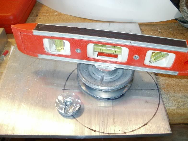
TC, if I'm reading the above right, you're basically depending on friction between the rotor/spacer and spacer/pulley to stabilise the pulley. While that would help some, I think long-term you'd still have the same problem. But you're on the right track.
If it were me, I'd try this:
[IMG]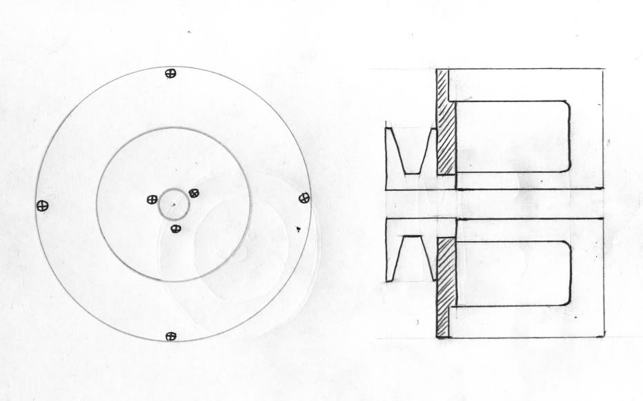 [/IMG]
Now, this isn't in anything close to scale, just a quick scribble.
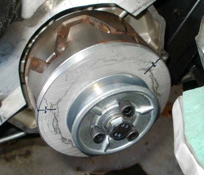
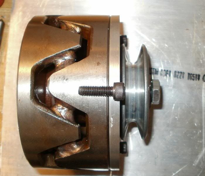
Machine your 'spacer' (the shaded part) so it fits partially into the rotor; a light interference fit would be good. Take the pulley, and machine the long hub to a uniform size. Bore the spacer the same size or a few thou under, press the pulley into the spacer. Now your pulley is located wholely by the spacer/rotor; the bolt is now simply retaining it. I think if you assembled this with red locktite on the pulley hub and at the rotor/spacer joint, that may take care of the set screw, but if not, you could put some small (say, 10-24) screws into the edge of the rotor and through the pulley to take care of the shear forces. If you spaced these equally, that would eliminate any balance problems. This also shortens the pulley and bolt, giving a slightly less wide assembly.
Admittedly, this is no longer doable in your garage with a rock and a stick, but the required machining is simple (i.e. reasonably cheap) and wouldn't add a huge $ outlay to the total. The drilling/tapping for the screws could be done at home, so you really only need the spacer/pulley machined. You may be able to find a pulley that already has the right type hub, so now all you need is the spacer...
If it were me, I'd try this:
[IMG]
[/IMG]Now, this isn't in anything close to scale, just a quick scribble.
Machine your 'spacer' (the shaded part) so it fits partially into the rotor; a light interference fit would be good. Take the pulley, and machine the long hub to a uniform size. Bore the spacer the same size or a few thou under, press the pulley into the spacer. Now your pulley is located wholely by the spacer/rotor; the bolt is now simply retaining it. I think if you assembled this with red locktite on the pulley hub and at the rotor/spacer joint, that may take care of the set screw, but if not, you could put some small (say, 10-24) screws into the edge of the rotor and through the pulley to take care of the shear forces. If you spaced these equally, that would eliminate any balance problems. This also shortens the pulley and bolt, giving a slightly less wide assembly.
Admittedly, this is no longer doable in your garage with a rock and a stick, but the required machining is simple (i.e. reasonably cheap) and wouldn't add a huge $ outlay to the total. The drilling/tapping for the screws could be done at home, so you really only need the spacer/pulley machined. You may be able to find a pulley that already has the right type hub, so now all you need is the spacer...
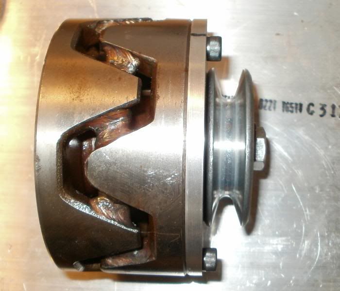
 Yeah, I could machine it to a truer cylinder but that's again adding a machining step!
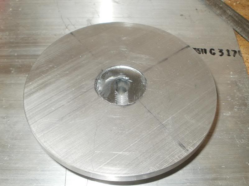
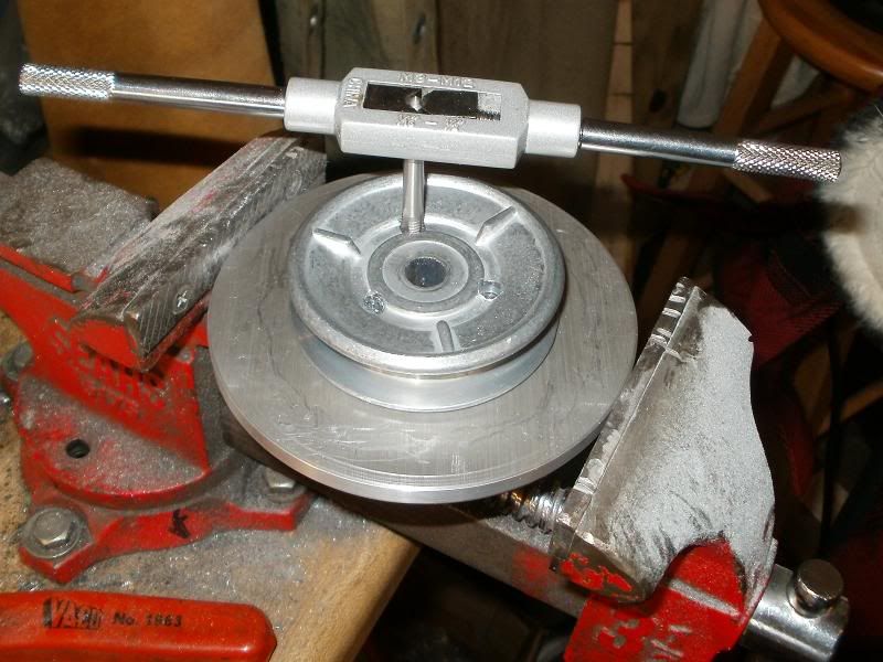
 ") A slower way of making the PLATE interference hole would be to use a slightly narrower drill bit, and then either a dremmel stone or round/curved file to make the slight taper contour for the pulley hub...again trying to avoid fancy machine tools.
A slower way of making the PLATE interference hole would be to use a slightly narrower drill bit, and then either a dremmel stone or round/curved file to make the slight taper contour for the pulley hub...again trying to avoid fancy machine tools. 
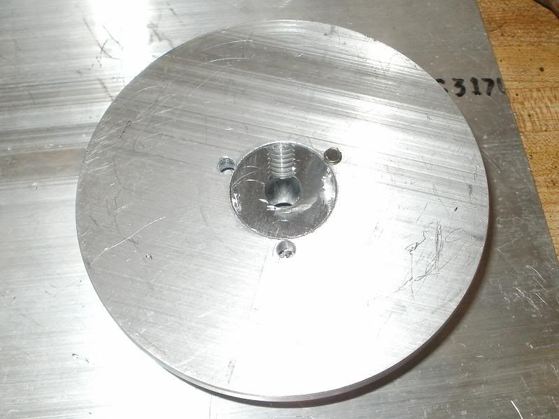
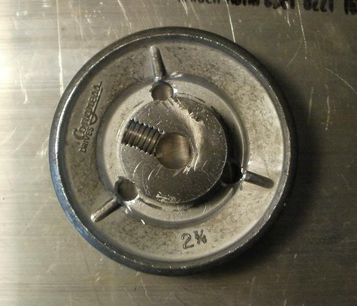
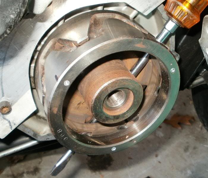
 Fortunately I caught it before I sheared it in half! The new set had matching drill bits, and that also contributed in a slightly easier and successful tapping, since the drill bit for the 6mm tap was 13/64" instead of the 3/16=12/64" I had first used! With STEEL, having less material to break as chips goes a long way!
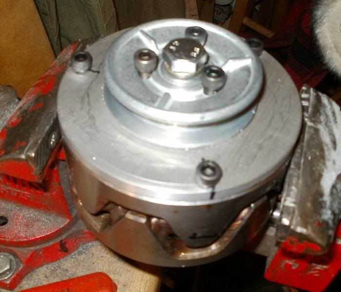


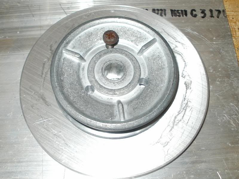
 Just showing for the sake of others perhaps not as familiar with the lingo!


Comment