
Great job
You do nice work James, I think your looking at another big check !!!!!
-
Little update
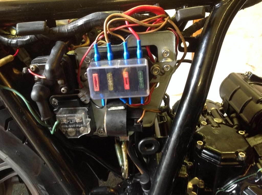
Got a few bits and bobs done on the project. I got the drive gearbox on and shaft drive connected up. The wiring harness is now on and the blade fuse box installed and running. Amazingly, almost everything seems to work, including the neutral light which didn't work until I bought a new switch.
One minor glitch is the lights on/off switch. It works fine on the sidelight setting but blows the fuse, even if the headlamp is not actually plugged in. I'm assuming that my recent rebuild of the handlebar switch is what's caused it, with a short somewhere, possibly. At this stage though, that can wait. Of course, I can't test the charging side of things but it was all working before the strip down so hopefully all will be well on the big day.. Which is a way off yet!
The engine turns over fine with the plugs out, so the next stage is to get the oil cooler renovated, reconnected, then put oil in the engine.......
Onwards and upwards...
Here's a pic of the blade fuse box..a well worthwhile modification....
Gearbox in

Starting to look like a motor sickle again...

 Last edited by James England; 07-20-2014, 09:13 AM.
Leave a comment:
-
Duh....and the 'Incompetent of the Year Award 2014' goes to James England. Let's hear a big round of applause everyone and ask ourselves if he really knows what he's doing....
The component fits on the left side of the bike, under the side panel. I'd been looking for a lug with a threaded hole but the one this bit attaches to is just a lug with an unthreaded hole in it......

Leave a comment:
-
Another rebut for help!
Despite working on several of these bikes, I'm having a 'senior moment' ...again....
So, I now have the fuse box assembly installed and awaiting connection to the main wires. But...I have one component left and it's very clear where it plugs into the wiring loom but.... I cannot for the life of me remember where it physically fits on the bike! It doesn't go under the right side panel. It has a clip on it for a pipe of some sort and it also has locating lugs on the bracket to stop it rotating when it's fitted to wherever its supposed to go.
Here's a pic.... Can anyone please tell me where it physically fits on the bike before I go completely mad.

Leave a comment:
-
Heh heh! I'm pleased my efforts are appreciated as it's all good fun to do for our little brotherhood (and our sister Wildkat, of course).
I found the lost earthing strap, hidden away so securely that I couldn't find it for ages. One good thing is that, when I ransacked the workshops, I found a European gearbox cover that takes the gearchange linkage we have over here. Annoyingly, on the last set of conversion parts I sent to the US, I couldn't find the danged thing and ended up buying another one!! Hey oh...now I have a spare, if anyone's interested.Leave a comment:
-
Thanks fellas. All I have to do now is find that danged strap in the workshop.
Re bolts...no, I wouldn't use the original bolts for anything really. I know some restorations are done using original bolts and screws etc but personally, I think that's taking things too far. I always replace everything with stainless Allen bolts. The real purists would say that's not original but, then again, if you get a respray done, the paint isn't original either. Same goes for improvements like the Geezer rectifier/regulator or the blade fuse box.
My own particular mission statement on restoring these bikes is to make them better than original is some ways, whilst still looking mostly authentic. I did have one person comment on the last bike I did (Black Beauty) that the Allen bolts on the engine casings didn't have the milling round the edge which OEM had and that, as a result of that, it wouldn't win some competition or other that he mentioned. My response was "so what?". It didn't stop the bike selling for a most $8,000 either...
Onwards and upwards with this one. There's still a lot to do but at least it's beginning to look like a motorbike again.......Leave a comment:
-
James,
It looks good from here!
Don't coil the extra length of Green wire, tuck out of the way behind the Fuse Panel and ensure that it can't rub against the frame or anything else.
Unless you're going for 100% factory original, replace that stupid galvanized Phillip's head frame ground screw with a galvanized hex head bolt and put a little dielectric grease on the connection before you cinch it up.
The engine ground strap goes underneath the short hex head bolt on the upper right-hand corner of the Middle Drive. Give it a little dielectric grease too before you torque it down.
.Leave a comment:
-
Ahhh, But to Captain Unobtainium this should be but a minor challenge. If I send you a popsicle stick and a match you might come up with something magical! Just a wee bit of a hard time to let you know we all appreciate your efforts on this site.
Leave a comment:
-
-
Thanks Scott. The difference in colour is what foxed me. I thought they had to be the same colour as it seemed wrong to have two drastically different colours joined together. Also, I wrongly thought the black/green wire went to the negative terminal of the battery instead of to the starter solenoid. I should have realised by the shape of the rubber shroud on the black/green wire, shouldn't I?
So, I now have a blade fuse box installed, with the green black wire attached to one of the starter solenoid terminals (with the other terminal connected to the positive terminal of the battery) and the thin green wire male bullet connector connected to the red/yellow female bullet connector. As per the pic below....l correct?
All I have to do now is remove all the in-line fuses and connect up the blade fuse box. The mess of wiring is draped over the top frame tube in the pic...

Ps here's the bike so far... The rear fender is on mainly to support the TCI box and to check the electrics. Then I'llremove it and clean it properly before reinstalling......

One other question, if you don't mind..... Where does the earthing strap fit from the engine to the frame? I can't remember and, annoyingly, I put the little strap sew here safe...so safe that I can't find it!Last edited by James England; 07-13-2014, 05:03 PM.Leave a comment:
-
James,
The Green and Black wire are Positive and go to the Starter terminal on the solenoid.
The Red/Yellow wire plugs into the Green wire and runs up to the TCI to bypass the ignition ballast resistor when starting the engine.
The Project is looking good! Have fun!
.Leave a comment:
-
Request for help
Hey folks..... I neglected to take pix of the wiring harness when I took it off the bike. Stupid really. I've got most of it back but I have a few rogue wires in the harness which don't appear to match up to anything that needs to be put back onto the bike.....
Here's one... A red and yellow wire coming out of the wiring harness, with a male bullet connector on it.......

The other one is attached to the negative wire to the battery... A green wire with a female bullet connector on it....

These two have me stumped! Any ideas anyone?Leave a comment:
-
-
James, if you could get some exhausts available like bearings they would sell well I think. I know I'd buy one.
JohnLeave a comment:


Leave a comment: