XS11 "SPECIAL" front brake/fork Upgrade Mod
Hey folks,
As you might be able to gleen from the title of this soon to be marathon post, I have embarked on an expedition of unknown frustration!
My front caliper's pistons had become frozen after some 12 years after my last rebuild/cleaning. So...I tore them down to clean and rebuild them again, but I discovered more severe pitting in the pistons than had been then previously, and would need to replace them. I had seen Crazy Steve's Standard Fork caliper mod with the Harley dual piston calipers and a simple mounting adapter bracket and a "little" modding of the calipers themselves. I thought I would attempt to do a similar mod for the Special, to get rid of those funky slanted pads, and to put some modern dual piston calipers up there, not so much as to be able to do a STOPPIE , but to have more modern serviceable parts, pads and such...and hopefully get a little more braking power!
I first measured the clearance between the inside edge of the Rotor, and the wheel spokes, and found it to be about 41mm. I was concerned about clearance for the more modern 4 piston systems, as well as the need for possible modding to allow room for our thick 7mm rotor vs. modern bikes which have ~4mm thick rotors. So..I decided to look for a dual piston design. There were plenty of 4 piston units from Yamaha FZ type bikes, but I found a set off an '05 FZR600 with only 2 pistons per caliper. I didn't know how thick/big it was from the edge of the inside brake pad to the edge of the caliper housing, but I figured it would be narrower than a 4 piston system, I took a gamble and ordered them from ebay. ~$50.00 for the pair plus S&H. That's about how much I would have had to spend on just the replacement OEM special pistons, not to mention rebuild kits! And the calipers came with the brake pads, almost new thickness, and they were organic fiber, not metal sintered type.
Once I received the calipers, I could then proceed with the design for the adapter/bracket. The special uses a fairly pronounced buttress that has a groove for the brake pads to slide in and provides most of the strength of the brake pads stopping power, the single 8mm bolt through the special's caliper is just to hang the swivelly caliper and slanted pads around the rotor, wedging the pads against the buttress... so the bolt doesn't have much stress on it.
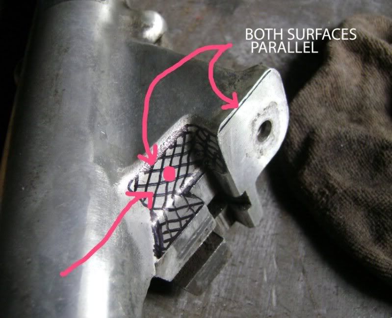
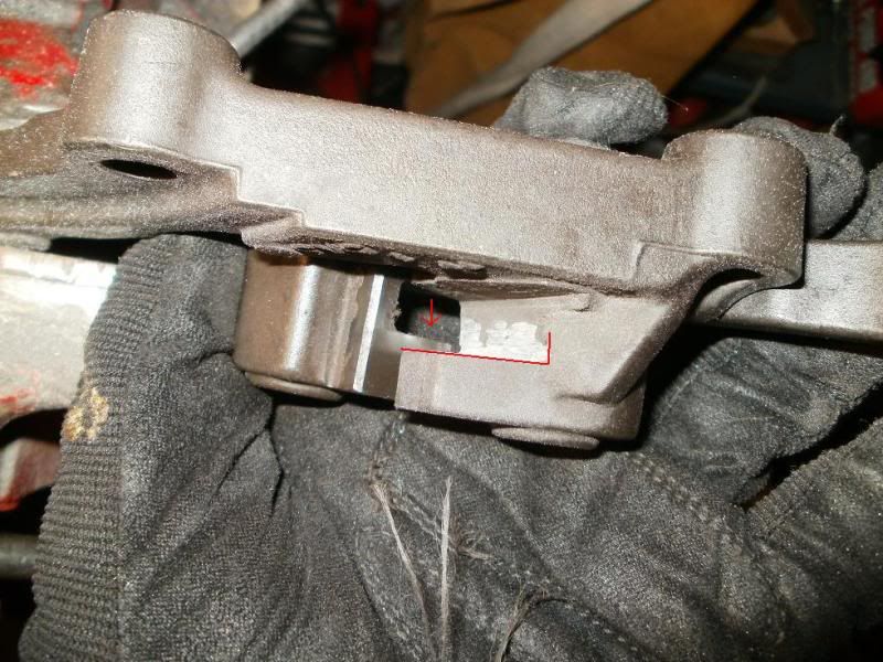
I had first thought about trying to keep the forks STOCK, both trying to come up with a bracket design that could be fashioned at home with simple tools and also allow the option of going back stock if desired! Below are a series of photos showing the fork buttress area, the pads groove, the Z shaped recess from the OEM bolt plate location down into the buttress area, etc.!
I had some 1" thick aluminum plate material, and was thinking about cutting 1/2 of it's thickness away to fit alongside the large buttress plate as well as into the recesses of the buttress, etc.!
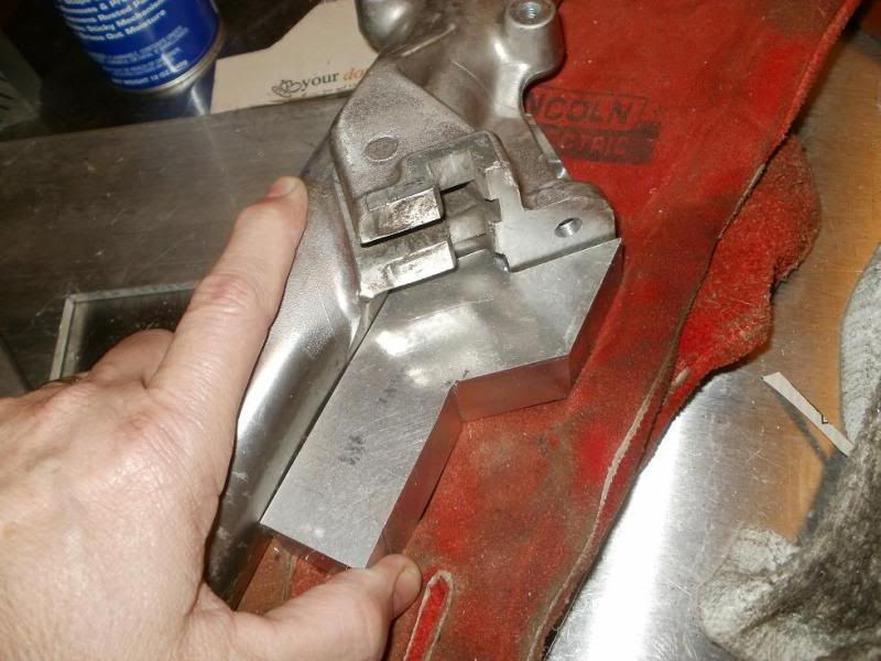
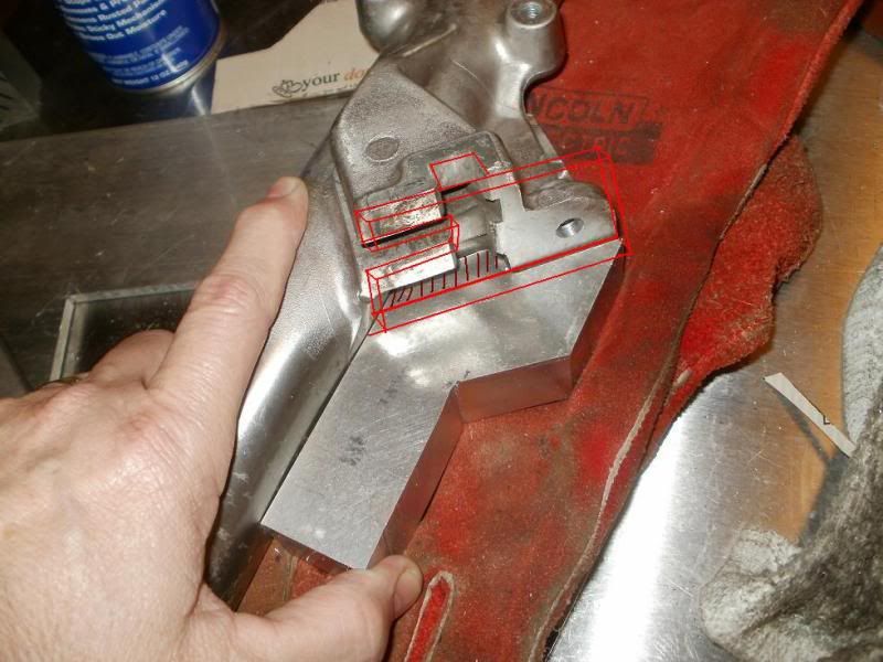
However, due to the casting imperfections, the edge of that buttress wasn't at a true 90 degrees to the mounting bolt plate.
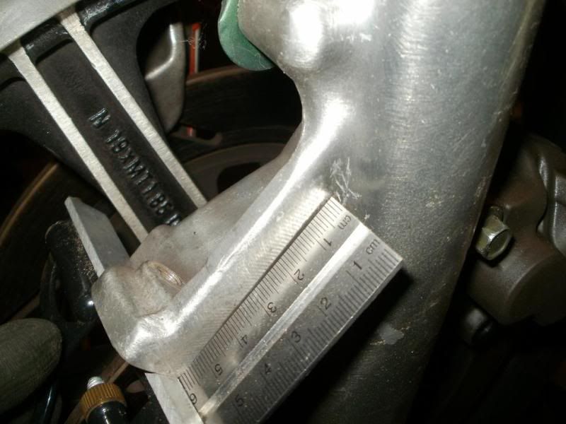
A few other mockups with the preliminary bracket piece, already getting complicated!
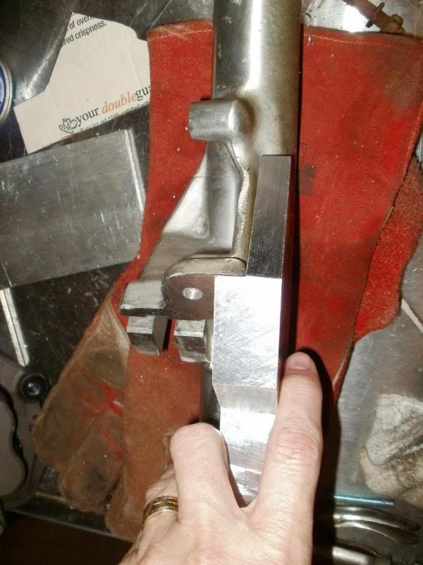
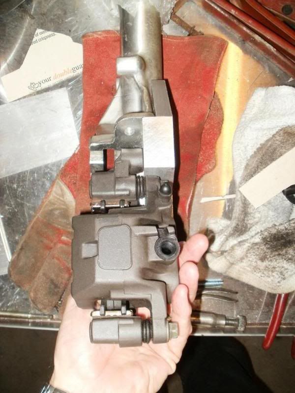
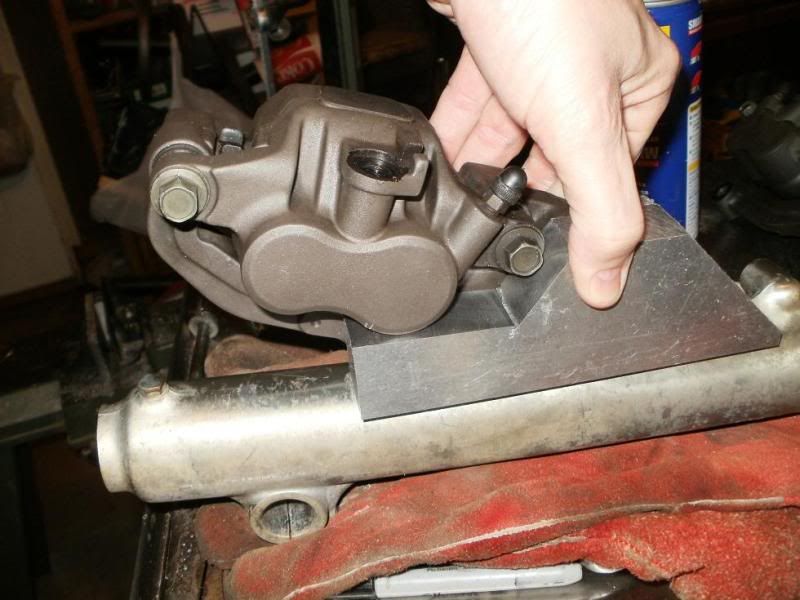
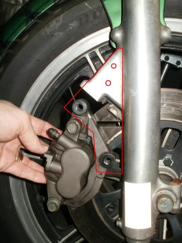

And as shown above, I was still looking at the possibility of needing an additional plate to go across the entire mounting area, etc.! I wasn't thinking out of the box, I was limiting myself to the material I had on hand...1" thick plate!
Then I realised that I would NOT be going back to stock with this mod, and that it most likely will not be an easy do it yourself bolt on type mod, so I decided to open up my options to design and fabrication. Crazy Steve was very instrumental in assisting me in thinking outside of the box, and without the constraints of going back stock, we made some drastic design changes.
I also had a log of 4" thick x 6" long aluminum I was saving for another project, but decided I could use it to provide some thicker/wider material for the new design. Without the constraints of STOCK, Steve first suggested that the inner rotor guide be removed from each fork slider.
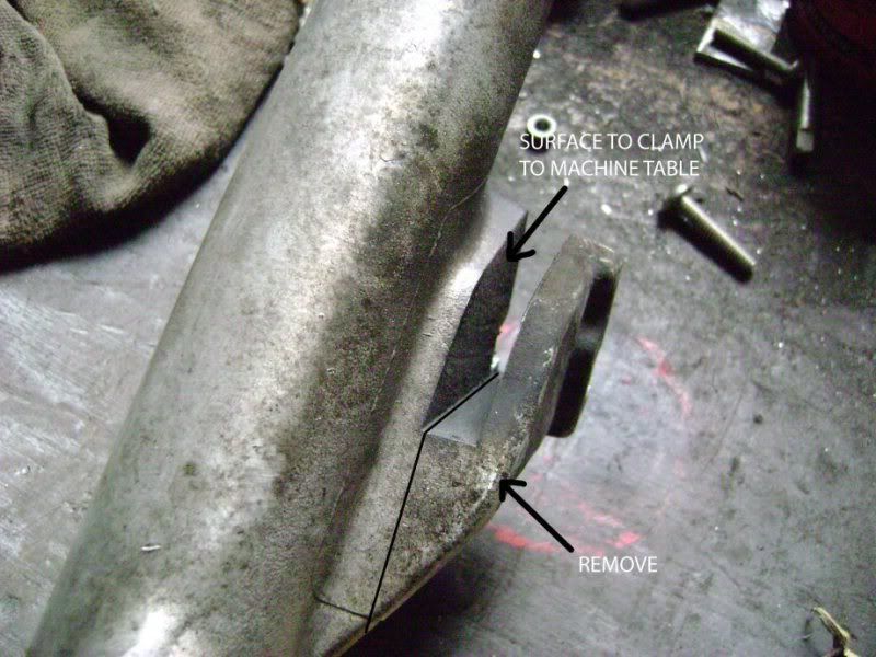
Then, to simplify the attachment area, the area below the OEM bolt contact plate would need to be removed to make a more simpler 2 level surface with just one 90 degree bend/step between them.
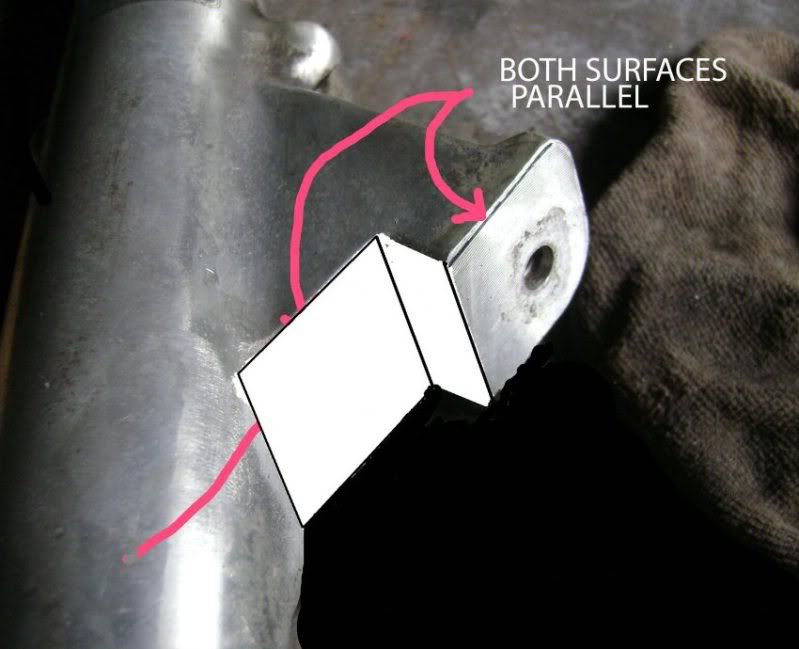
With this in mind, I started on the rework of the design and the fork modding. I used a metal cutting band saw to remove the inner rotor guide from each fork slider.
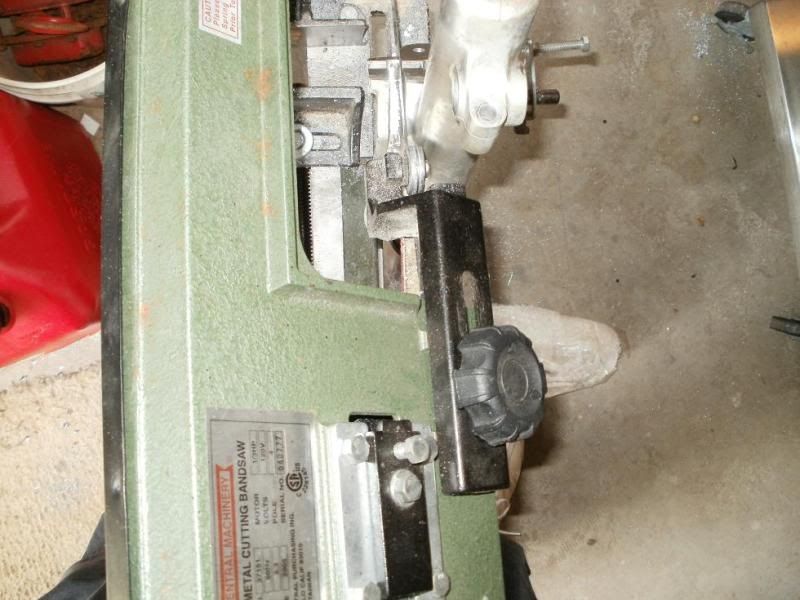
This shows the area that is to be machined/removed from the recess area of the fork.
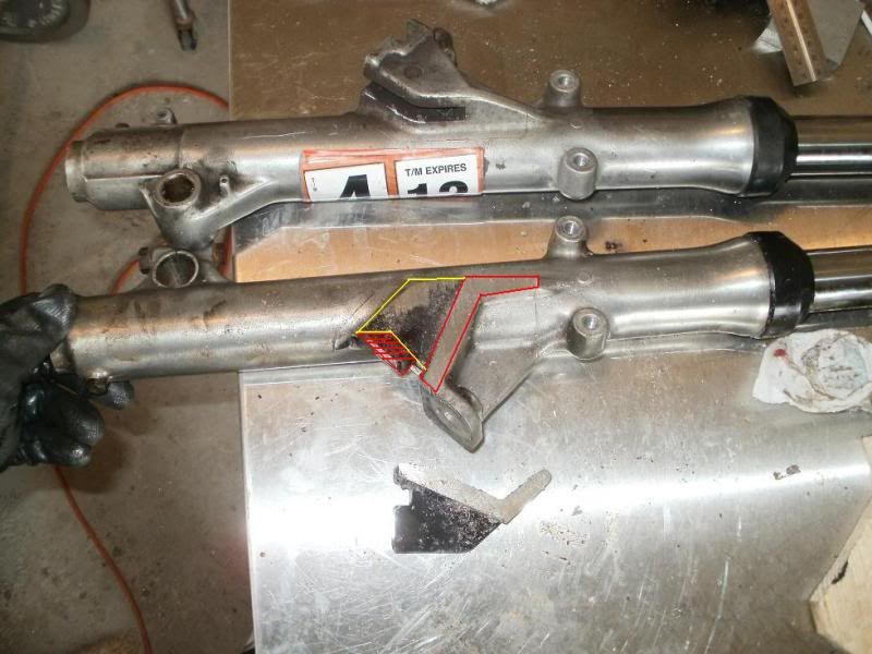
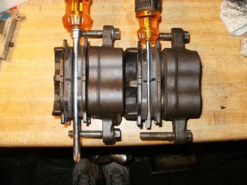
Back to the calipers, here are both of them, the one on the right was how it arrived, and it has a smaller ~4mm diameter screwdriver stuck between the pads, and I noticed that there was some piston protruding from the caliper housing, and I hoped that they were just stuck there due to the smaller rotor they were used to being around, and once I pulled the other one down, removed the dirt/grime, cleaned and relubed the O-ring with brake fluid, the pistons went back in much farther, and you can see by the one on the left that there's more room between the pads by example of the larger ~7mm diam. screwdriver placed between those pads! Okay, first clearance problem solved, will fit around the XS's 7mm wide rotor without any $$ grinding work to thin the rotor!
Then I took the caliper bracket and placed it over the rotor to see how much clearance there was....not much!
This shows the amount I ground away from the inside edges of the caliper mount bracket to allow room for the rotor!
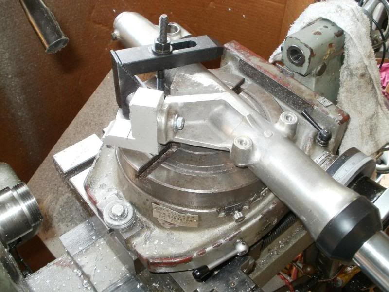
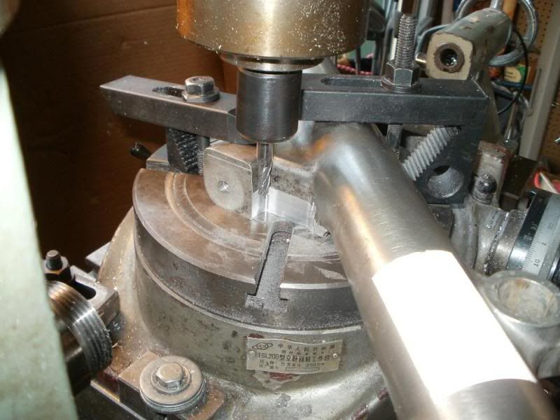
Next was on to the machining of the fork, I/we assumed that the OEM mounting plate surface was perpendicular(90) degrees to the direction of the whole fork, so I made a little jig that was measured to be 90 degrees on 2 sides, and bolted it to the fork, and then secured it to the machine/rotary table with additional clamps. I was then able to machine FLAT the rotor guide area.
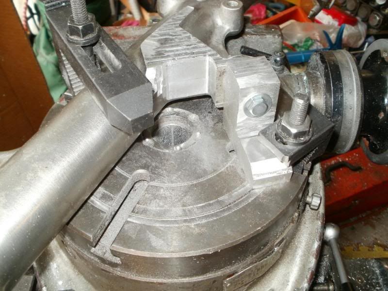
I was then able to use that machined flat surface to position the fork on it's other side to allow machining of the remaining recess area...my 1/4" diameter milling bit wasn't long enough to do the whole recessed area without flipping the fork over!
This is just the second fork showing the entire recessed area machined flat like in Steve's earlier diagram.
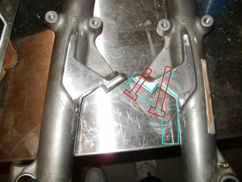
Here are both forks, recessed areas machined, and showing the plan for the placement of the larger securing bolts to hold the adapter brackets for the calipers!
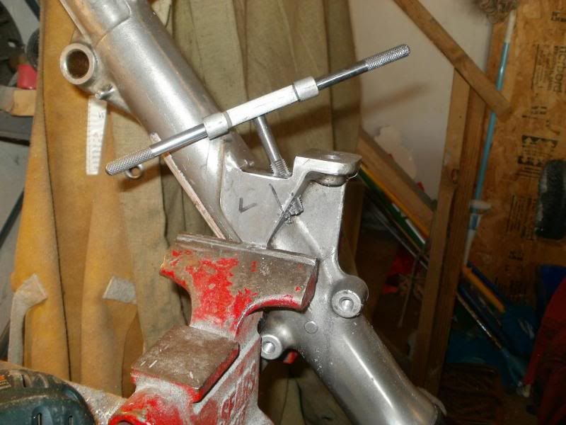
Drilling and tapping the 10mm x 1.25 pitch was a challenge in that location of the fork, as well as at that angle!
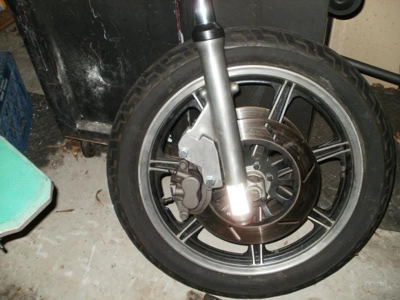
Next are a few photos of the finished adapter bracket alone and then mounted to the fork.
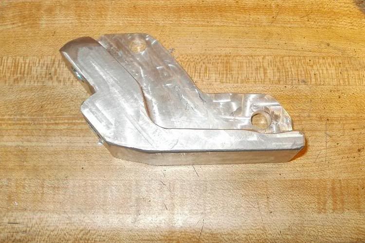
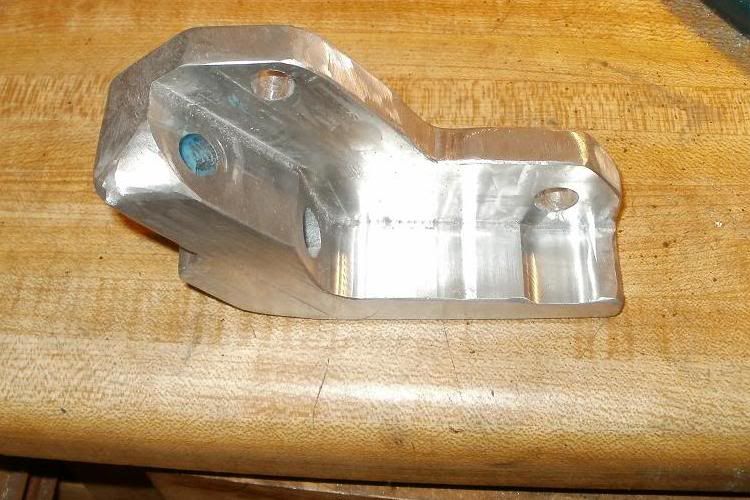
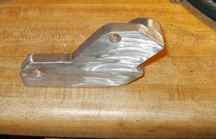
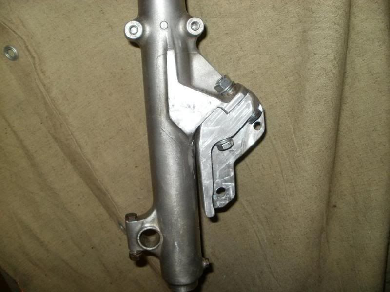
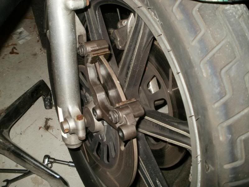
Here's the right caliper mounted up to the fork/wheel while they are still not connected to the frame for a mock up!
(Continued in next post....went beyond the 30 images per post limit!)
Hey folks,
As you might be able to gleen from the title of this soon to be marathon post, I have embarked on an expedition of unknown frustration!
My front caliper's pistons had become frozen after some 12 years after my last rebuild/cleaning. So...I tore them down to clean and rebuild them again, but I discovered more severe pitting in the pistons than had been then previously, and would need to replace them. I had seen Crazy Steve's Standard Fork caliper mod with the Harley dual piston calipers and a simple mounting adapter bracket and a "little" modding of the calipers themselves. I thought I would attempt to do a similar mod for the Special, to get rid of those funky slanted pads, and to put some modern dual piston calipers up there, not so much as to be able to do a STOPPIE
 , but to have more modern serviceable parts, pads and such...and hopefully get a little more braking power!
I first measured the clearance between the inside edge of the Rotor, and the wheel spokes, and found it to be about 41mm. I was concerned about clearance for the more modern 4 piston systems, as well as the need for possible modding to allow room for our thick 7mm rotor vs. modern bikes which have ~4mm thick rotors. So..I decided to look for a dual piston design. There were plenty of 4 piston units from Yamaha FZ type bikes, but I found a set off an '05 FZR600 with only 2 pistons per caliper. I didn't know how thick/big it was from the edge of the inside brake pad to the edge of the caliper housing, but I figured it would be narrower than a 4 piston system, I took a gamble and ordered them from ebay. ~$50.00 for the pair plus S&H. That's about how much I would have had to spend on just the replacement OEM special pistons, not to mention rebuild kits! And the calipers came with the brake pads, almost new thickness, and they were organic fiber, not metal sintered type.
Once I received the calipers, I could then proceed with the design for the adapter/bracket. The special uses a fairly pronounced buttress that has a groove for the brake pads to slide in and provides most of the strength of the brake pads stopping power, the single 8mm bolt through the special's caliper is just to hang the swivelly caliper and slanted pads around the rotor, wedging the pads against the buttress... so the bolt doesn't have much stress on it.
I had first thought about trying to keep the forks STOCK, both trying to come up with a bracket design that could be fashioned at home with simple tools and also allow the option of going back stock if desired! Below are a series of photos showing the fork buttress area, the pads groove, the Z shaped recess from the OEM bolt plate location down into the buttress area, etc.!

I had some 1" thick aluminum plate material, and was thinking about cutting 1/2 of it's thickness away to fit alongside the large buttress plate as well as into the recesses of the buttress, etc.!


However, due to the casting imperfections, the edge of that buttress wasn't at a true 90 degrees to the mounting bolt plate.

A few other mockups with the preliminary bracket piece, already getting complicated!


And as shown above, I was still looking at the possibility of needing an additional plate to go across the entire mounting area, etc.! I wasn't thinking out of the box, I was limiting myself to the material I had on hand...1" thick plate!
Then I realised that I would NOT be going back to stock with this mod, and that it most likely will not be an easy do it yourself bolt on type mod, so I decided to open up my options to design and fabrication. Crazy Steve was very instrumental in assisting me in thinking outside of the box, and without the constraints of going back stock, we made some drastic design changes.
I also had a log of 4" thick x 6" long aluminum I was saving for another project, but decided I could use it to provide some thicker/wider material for the new design. Without the constraints of STOCK, Steve first suggested that the inner rotor guide be removed from each fork slider.

Then, to simplify the attachment area, the area below the OEM bolt contact plate would need to be removed to make a more simpler 2 level surface with just one 90 degree bend/step between them.

With this in mind, I started on the rework of the design and the fork modding. I used a metal cutting band saw to remove the inner rotor guide from each fork slider.

This shows the area that is to be machined/removed from the recess area of the fork.

Back to the calipers, here are both of them, the one on the right was how it arrived, and it has a smaller ~4mm diameter screwdriver stuck between the pads, and I noticed that there was some piston protruding from the caliper housing, and I hoped that they were just stuck there due to the smaller rotor they were used to being around, and once I pulled the other one down, removed the dirt/grime, cleaned and relubed the O-ring with brake fluid, the pistons went back in much farther, and you can see by the one on the left that there's more room between the pads by example of the larger ~7mm diam. screwdriver placed between those pads! Okay, first clearance problem solved, will fit around the XS's 7mm wide rotor without any $$ grinding work to thin the rotor!

Then I took the caliper bracket and placed it over the rotor to see how much clearance there was....not much!

This shows the amount I ground away from the inside edges of the caliper mount bracket to allow room for the rotor!

Next was on to the machining of the fork, I/we assumed that the OEM mounting plate surface was perpendicular(90) degrees to the direction of the whole fork, so I made a little jig that was measured to be 90 degrees on 2 sides, and bolted it to the fork, and then secured it to the machine/rotary table with additional clamps. I was then able to machine FLAT the rotor guide area.

I was then able to use that machined flat surface to position the fork on it's other side to allow machining of the remaining recess area...my 1/4" diameter milling bit wasn't long enough to do the whole recessed area without flipping the fork over!

This is just the second fork showing the entire recessed area machined flat like in Steve's earlier diagram.

Here are both forks, recessed areas machined, and showing the plan for the placement of the larger securing bolts to hold the adapter brackets for the calipers!

Drilling and tapping the 10mm x 1.25 pitch was a challenge in that location of the fork, as well as at that angle!


Next are a few photos of the finished adapter bracket alone and then mounted to the fork.


Here's the right caliper mounted up to the fork/wheel while they are still not connected to the frame for a mock up!

(Continued in next post....went beyond the 30 images per post limit!)
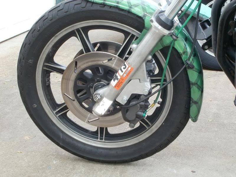
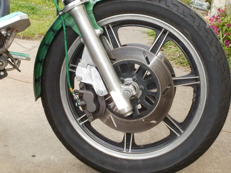
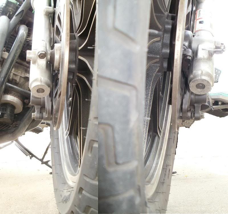


 This ain't easy, but then again it's not all that hard if you have the tools...


Comment