Here's another 'tutorial' to help the 'electrically challenged' among us. I'll talk here about volt-ohm meters (VOMs) and what all the 'stuff' on them means. Part 3 I'll go over how to use one, specifically for our wiring. If you have the owners manual for your meter, be sure and read it thoroughly.
For most of us, you'll have or will want to get a hand-held meter. There's all sorts out there, you may have one you've inherited, but there's two basic types; the analog meter and the digital meter. Here's a pic of the two types...
[IMG] [/IMG]
The analog is on the left, the other two are digital. Both types will work for our purposes, but the analog type takes much better attention to reading it to get reasonable accuracy and usually can't match a good digital for that. One advantage analog has over some digital meters is it will 'read' moving values, while most digital meters take a moment to stabilise before giving a reading. I'll talk more about this in a moment. I'm not going to go into the analog type much due to their rarity these days.
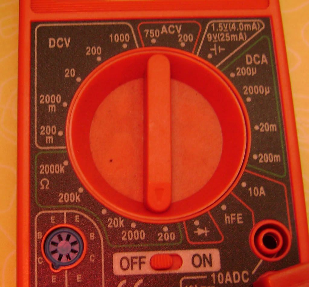
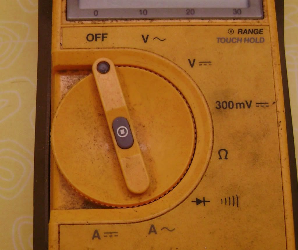
So how do you 'set' the meter to get readings? Here's pics of the two digital meter selector switches...
[IMG] [/IMG]
[IMG] [/IMG]
The top meter is a full-manual meter (and a analog meter will be similar); you have to turn the selector switch to the value you want to measure. You do have to take care here on live circuits, as using a wrong setting can kill the meter, such as selecting a 20 volt scale then trying to measure a voltage above that amount. The lower meter is a 'auto-ranging' type; it will automatically select the correct range, although this model also allows manual selection if desired (a very good feature to have). On the red meter, the test positions you'll be using will be the 20 DCV, the 200, 2000, and 20K ohm, the latter two for checking the ignition coils and spark plug caps only. You may also use the diode position once in a while to check the rectifier/regulator and the harness diode on the '80-81 bikes. On the yellow meter, the positions are (clockwise from 'off') AC volts, DC volts, 300 Millivolts, ohms, diode test, and AC then DC amps. Again, you'll be using the DC volts and ohms, and the diode test rarely. The button in the middle of the selector switch is for manually selecting range.
Ok, What's the reading on the display mean? We'll start with the manual meter...
[IMG] [/IMG]
In this case, the meter is set to the '200' ohm scale, so you'll get a direct reading in ohms of whatever you're checking as long as it's resistance is under 200 ohms. If it's over that, the display won't change. As you increase the range, the meter won't be able to measure small amounts and a low resistance will show as zero. For 99% of the resistance checks you'll want to do on a bike, this is the scale you'll use. You'll get the best accuracy by using the lowest scale (without going under the measured value) for both ohms and voltage.
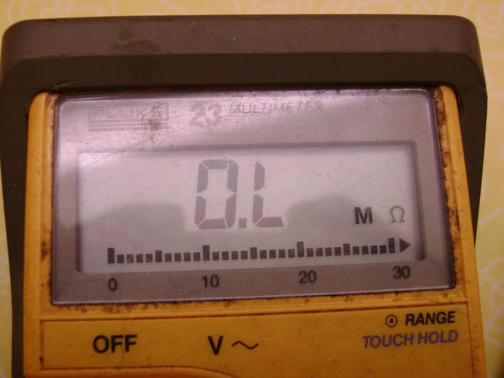
Here's the auto-range meter...
[IMG] [/IMG]
There's more stuff going on here; first, this meter displays the type of measurement you're making, in this case ohms. It's also putting a 'M' in front of it, which means it's set to measure megohms (millions). A 'K' would mean thousands, no letter is straight ohms. The 'OL' it's displaying means 'open line'. Being an auto-range type, it will automatically switch to a lower scale if it measures a low resistance. The other thing to note is the 'bar' at the bottom of the display; this is a 'analog' graph (giving you the same function as an analog meter for reading moving values), extremely useful to have. Voltage values will be read out directly.
Using the diode setting. You'll rarely use this unless you're checking a diode, unless you have a meter with an audible tone for testing. These can be used as a continuity tester (get a beep, you have continuity) but be aware that the numbers displayed ARE NOT in ohms; that's the pass-through voltage and when using as a circuit tester they'll usually show zero. To check for resistance, you must use a ohms scale. If testing a diode, typical values will be around .7 volt one direction only if the diode is good.
Meter accuracy. This is where quality shows when buying a meter. You want a meter with the best 'resolution' you can afford, particularly if measuring resistance. Good quality hand-held meters can measure down to .1 ohm accurately, cheaper meters won't do as well. I'll show why this is important when I explain how to use the meter, but don't let this prevent you from picking one up, as even the cheap ones can be useful. The red meter shown in the pics is a $3 (yep, three) unit from HF that checked very close to my more-expensive Fluke when I first brought it home, but a few months in my damp garage seems to have skewed it's readings some (hey, they warned to keep it dry so my bad), I'll see how it does after it dries out...
Any questions or comments welcome!
For most of us, you'll have or will want to get a hand-held meter. There's all sorts out there, you may have one you've inherited, but there's two basic types; the analog meter and the digital meter. Here's a pic of the two types...
[IMG]
 [/IMG]
The analog is on the left, the other two are digital. Both types will work for our purposes, but the analog type takes much better attention to reading it to get reasonable accuracy and usually can't match a good digital for that. One advantage analog has over some digital meters is it will 'read' moving values, while most digital meters take a moment to stabilise before giving a reading. I'll talk more about this in a moment. I'm not going to go into the analog type much due to their rarity these days.
So how do you 'set' the meter to get readings? Here's pics of the two digital meter selector switches...
[IMG]
 [/IMG]
[IMG]
 [/IMG]
The top meter is a full-manual meter (and a analog meter will be similar); you have to turn the selector switch to the value you want to measure. You do have to take care here on live circuits, as using a wrong setting can kill the meter, such as selecting a 20 volt scale then trying to measure a voltage above that amount. The lower meter is a 'auto-ranging' type; it will automatically select the correct range, although this model also allows manual selection if desired (a very good feature to have). On the red meter, the test positions you'll be using will be the 20 DCV, the 200, 2000, and 20K ohm, the latter two for checking the ignition coils and spark plug caps only. You may also use the diode position once in a while to check the rectifier/regulator and the harness diode on the '80-81 bikes. On the yellow meter, the positions are (clockwise from 'off') AC volts, DC volts, 300 Millivolts, ohms, diode test, and AC then DC amps. Again, you'll be using the DC volts and ohms, and the diode test rarely. The button in the middle of the selector switch is for manually selecting range.
Ok, What's the reading on the display mean? We'll start with the manual meter...
[IMG]
 [/IMG]
In this case, the meter is set to the '200' ohm scale, so you'll get a direct reading in ohms of whatever you're checking as long as it's resistance is under 200 ohms. If it's over that, the display won't change. As you increase the range, the meter won't be able to measure small amounts and a low resistance will show as zero. For 99% of the resistance checks you'll want to do on a bike, this is the scale you'll use. You'll get the best accuracy by using the lowest scale (without going under the measured value) for both ohms and voltage.
Here's the auto-range meter...
[IMG]
 [/IMG]
There's more stuff going on here; first, this meter displays the type of measurement you're making, in this case ohms. It's also putting a 'M' in front of it, which means it's set to measure megohms (millions). A 'K' would mean thousands, no letter is straight ohms. The 'OL' it's displaying means 'open line'. Being an auto-range type, it will automatically switch to a lower scale if it measures a low resistance. The other thing to note is the 'bar' at the bottom of the display; this is a 'analog' graph (giving you the same function as an analog meter for reading moving values), extremely useful to have. Voltage values will be read out directly.
Using the diode setting. You'll rarely use this unless you're checking a diode, unless you have a meter with an audible tone for testing. These can be used as a continuity tester (get a beep, you have continuity) but be aware that the numbers displayed ARE NOT in ohms; that's the pass-through voltage and when using as a circuit tester they'll usually show zero. To check for resistance, you must use a ohms scale. If testing a diode, typical values will be around .7 volt one direction only if the diode is good.
Meter accuracy. This is where quality shows when buying a meter. You want a meter with the best 'resolution' you can afford, particularly if measuring resistance. Good quality hand-held meters can measure down to .1 ohm accurately, cheaper meters won't do as well. I'll show why this is important when I explain how to use the meter, but don't let this prevent you from picking one up, as even the cheap ones can be useful. The red meter shown in the pics is a $3 (yep, three) unit from HF that checked very close to my more-expensive Fluke when I first brought it home, but a few months in my damp garage seems to have skewed it's readings some (hey, they warned to keep it dry so my bad), I'll see how it does after it dries out...
Any questions or comments welcome!

 Easier to read 45ohm on the screen, rather then look at the needle that is between 40ohm and 50ohm and wonder if it is exactly in the middle or not.


Comment