Announcement

Collapse
No announcement yet.

Alternative Alternator Options

Collapse
X
 
  • Filter
  • Time
  • Show
Clear All
new posts

  • #91
    Time to Chime in.

    Hey guys,

    Interesting tech discussion here, thanks.

    I used washers, because that's what I had on hand with this PROTOTYPE proof of concept fitment. I plan on replacing them behind the pulley with a piece of 1/2" thick aluminum plate drilled/machined to size. The PULLEY from Grainger is ZAMAK #3, pretty strong cast aluminum/zinc alloy. Also the 10mm x 100mm bolt is Metric Grade 8.8 = Standard Grade 5 at 120,000 psi tensile strength..again, I think plenty strong to secure the very snug pulley to bolt shaft fitting against the ROTOR.

    The ROTOR is quite heavy and well balanced already. The pulley is balanced as stated to 3600 rpm, so should be able to handle 7200 or more. I don't have a way to test how much tension is being put on the belt/pulley at the crank. With the heavy ROTOR acting as a flywheel, I would think it would actually help reduce the amount of perpendicular stress on the bearings induced by the belt's tension, and since it's a LOW DRAG ALT...it's meant for a race car application...least drag necessary=more HP to wheels...that the belt tension doesn't need to be terribly tight, it's a 1/2" wide belt, has plenty of grip with very little tension on it.

    Here's some interesting photos I had from a fellow that posted these way back in 2002 or 3. This is the highest resolution of the images I had, and so I can't see that well the center of the crank hub, but from the looks of the CUSTOM made Supercharger and plates $$$, that he's probably custom made a pulley HUB $$$ to mount onto the end of the crank/Rotor combo since he's keeping the OEM ALT cover...just made a hole in the center!
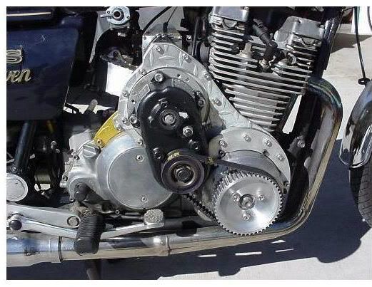
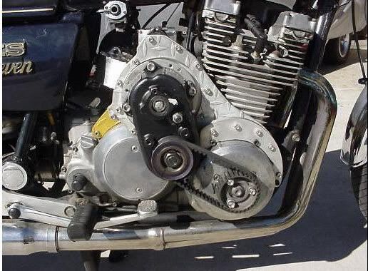


    I checked into the timing belt style recently, some findings: The round slot style was shown to withstand stresses and be stronger than the trapezoidal or square cut slots.

    The AUTO sized round "Radius Tooth HTD" spacing is 20mm center of tooth to tooth, and althouth they offer pulleys for Alternators...the Mini-Alt has a shaft ID of ~17mm/0.670"...the don't offer a similar sized pulley for the crank..they are all at least 0.50" or larger ID/Bore sizes...too big for the 10mm bolt. These toothed pulleys were found on a RACING PARTS site, and just the ALT pulley is over $60.00, not to mention the GUIDES were ~$30.00.

    The Econobelt and places I've seen with pulleys, have the Radius Tooth spacing at 8mm max! Then there's the problem of if you find a pulley with an ID bore size to fit the ALT, it's extremely LARGE Outer diameter size, and the ones to fit the crank's ID of 10mm...I could only find either 8mm or 12 mm, then they are very small or about the same size we have now, but you can't get a matching one for the ALT's Shaft!

    The ALT came with the V-groove, and I was able to find/source a comparable sized pulley that would fit with the use of the 10mm bolt for the crank/rotor location. Again, my goal was to be able to do this with the least $$ expendable, with off the shelf parts, tools, and prices for most budgets.

    I'm awaiting the receipt of the larger PLATE piece to redo the mount, positioning the ALT another 1/4" forward away from the clutch cable, and then to afix the better belt/pulley cover. The weather is getting a bit warmer and nicer...spring is starting to spring here, and with the soaring fuel prices...I may be forced to turn Godzilla into a daily work/commuter at 30mpg vs. my SUV's 18 ! So...I may be giving this design a longer test run sooner than I anticipated!

    I will say though, if anyone can source the radius toothed pulleys in the 2-3" overall diameter size and have the required ID's of 10mm AND 17mm for the crank and ALT, tell me where and I'll be happy to acquire the parts. I know they make the belts in the ~20"...508mm length size needed with a ~2.75" diam set of crank/alt pulleys.

    T.C.
    T. C. Gresham
    81SH "Godzilla" . . .1179cc super-rat.
    79SF "The Teacher" . . .basket case!
    History shows again and again,
    How nature points out the folly of men!

    Comment


    • #92
      TC, if you did a machined spacer for the pulley that engaged on the rotor that would go a long ways to removing a lot of the stress on that bolt. The rotor has a machined hub, so maybe make your spacer thicker and counterbore it so it fits over the rotor hub. A light interference fit would be even better. If you machined the pulley so it went into the spacer too (sort of a combo spacer/sleeve) that would support that bolt much better.

      As far as the pulleys, you can always make a small bore larger, so that's not insurmountable. The main thing I'd be concerned about is if the belt can take the load. Remember, that load is calculated on a given belt tension, so if you start screwing with that, you may be throwing the load rating out the window. My Sportster uses a belt final drive, and that belt is damned tight when adjusted correctly. Too loose, and it'll eat the teeth right off it.

      As far as load, you've said this is a 'low drag' unit but what you need to remember is that really only refers to friction losses from the brushes and bearings. It still takes 1 hp to produce 746 watts (assuming no losses, either electrical or mechanical), so at full 40A output, you'll be applying 3/4 hp to that belt at least, not figuring any other drag. Those 'timing belts' that Cy linked to aren't really designed for power transmission, but are more for keeping the various parts of a machine 'in time'. Again, you'd really need to check their rating before using them in this application.

      You've proven the electrical portion of this swap (me 'at's off to you guv!), now you just need to 'refine' the mount/drive....
      Fast, Cheap, Reliable... Pick any two

      '78E original owner - resto project
      '78E ???? owner - Modder project FJ forks, 4-piston calipers F/R, 160/80-16 rear tire
      '82 XJ rebuild project
      '80SG restified, red SOLD
      '79F parts...
      '81H more parts...

      Other current bikes:
      '93 XL1200 Anniversary Sportster 85RWHP
      '86 XL883/1200 Chopper
      '82 XL1000 w/1450cc Buell, Baker 6-speed, in-progress project
      Cage: '13 Mustang GT/CS with a few 'custom' touches
      Yep, can't leave nuthin' alone...

      Comment


      • #93
        Let me preface this by saying that i am not a machinist. In looking at the rotor, it looks like a bowl type affair could be turned out to be a tight slip fit over the rotor, and possibly inside as well. It could have a 10MM bore recessed in. This would leave room on the outside surface to mount a serpentine type pulley with 3 or 4 bolts. I don't think you would be affecting the rotor, and give a more stable mount for the pulley.
        1980 XS1100LG Midnight
        1991 Honda CBR1000F Hurricane


        "The hand is almost valueless at one end of the arm if there be not a brain at the other"

        Here's to a long life and a happy one.
        A quick death and an easy one.
        A pretty girl and an honest one.
        A cold beer and another one!

        Comment


        • #94
          Just found this website with pulleys and belts. Might be worth looking at.
          http://www.sdp-si.com
          1980 XS1100LG Midnight
          1991 Honda CBR1000F Hurricane


          "The hand is almost valueless at one end of the arm if there be not a brain at the other"

          Here's to a long life and a happy one.
          A quick death and an easy one.
          A pretty girl and an honest one.
          A cold beer and another one!

          Comment


          • #95
            Originally posted by XS1100 Newbie View Post
            Just found this website with pulleys and belts. Might be worth looking at.
            http://www.sdp-si.com
            These folks also seem to have a good line of timing pullies

            http://www.fnsheppard.com/pulleys.htm

            Steve has a good point though. The price of electrical output is mechanical input. One item that I did not see on the several sites I scanned through was any sort of tension or radial load rating for these pullies (or belts). When I get home tonight I'll take a look at the old Machinery's Handbook and see if it has any words of wisdom on the subject.
            John (XSive_Speed)

            '80 XS1100G Standard
            - 4 - 1 exhaust (probably Mac)
            - UNI air filter

            Comment


            • #96
              T.C., I love the picture of that blown XS engine!

              Given your experience with mounting the alternator my idea might not work because of the space limitation behind the cylinders: cut off the rotor poles and leave the outer face of the rotor along with the rotor hub to fit the tapered crankshaft end, then fit a bushed pulley over the rotor hub. Even if I had to cut the face off the rotor to get the pulley --> alternator alignment correct it should not be too bad.

              The hard part would be fitting a bushing to the existing rotor hub with a pulley to keep the alternator at 1:1 for the tachometer but I found a site describes almost exactly what I had in mind:-

              Bushed Pulley

              I have the fairing lowers installed right now so I can't eyeball the alternator in place and it would not be easily reversible like your modification.
              -- Scott
              _____
              ♬
              2004 ST1300A: No name... yet
              1982 XJ1100J: "Baby" SS Brakes, '850 FD, ACCT
              1980 XS1100G: "Columbo" SS Brakes, '850 FD, ACCT
              1979 XS1100SF: "Bush" W.I.P.
              1979 XS1100F: parts
              2018 Heritage Softail Classic 117 FLHCS SE: "Nanuk" It's DEAD, it's not just resting. It is an EX cycle.
              ♬

              Comment


              • #97
                And if your cutting parts off the rotor you will have to have it rebalanced. Even at half the size it is still a lot of mass.
                Nathan
                KD9ARL

                μολὼν λαβέ

                1978 XS1100E
                K&N Filter
                #45 pilot Jet, #137.5 Main Jet
                OEM Exhaust
                ATK Fork Brace
                LED Dash lights
                Ammeter, Oil Pressure, Oil Temp, and Volt Meters

                Green Monster Coils
                SS Brake Lines
                Vision 550 Auto Tensioner

                In any moment of decision the best thing you can do is the right thing, the next best thing is the wrong thing, and the worst thing you can do is nothing.

                Theodore Roosevelt

                Comment


                • #98
                  Originally posted by natemoen View Post
                  And if your cutting parts off the rotor you will have to have it rebalanced. Even at half the size it is still a lot of mass.
                  I don't have a picture of an XS rotor (it's not nice to search and deep link to eBay auction images ) but it would be a much less than half the mass if I cut off the poles; cut off the outer face too and it's little more than a sleeve, no balancing required.
                  The more I look at T.C.'s simple mod the more work it looks like to chop up a perfectly good rotor.

                  I just don't want to use the same bolt to hold the pulley and an un-keyed rotor to the crankshaft. Sort of like Steve was thinking, it might be possible drill holes in a pulley from a scrap alternator and drill/tap the face of the rotor without cutting off the poles or using a sleeved pulley and I don't want to pay NASCAR prices for parts, either.
                  -- Scott
                  _____
                  ♬
                  2004 ST1300A: No name... yet
                  1982 XJ1100J: "Baby" SS Brakes, '850 FD, ACCT
                  1980 XS1100G: "Columbo" SS Brakes, '850 FD, ACCT
                  1979 XS1100SF: "Bush" W.I.P.
                  1979 XS1100F: parts
                  2018 Heritage Softail Classic 117 FLHCS SE: "Nanuk" It's DEAD, it's not just resting. It is an EX cycle.
                  ♬

                  Comment


                  • #99
                    For some reason I thought you said cut off half the poles...something is wrong with my brain...
                    Nathan
                    KD9ARL

                    μολὼν λαβέ

                    1978 XS1100E
                    K&N Filter
                    #45 pilot Jet, #137.5 Main Jet
                    OEM Exhaust
                    ATK Fork Brace
                    LED Dash lights
                    Ammeter, Oil Pressure, Oil Temp, and Volt Meters

                    Green Monster Coils
                    SS Brake Lines
                    Vision 550 Auto Tensioner

                    In any moment of decision the best thing you can do is the right thing, the next best thing is the wrong thing, and the worst thing you can do is nothing.

                    Theodore Roosevelt

                    Comment


                    • Scott,

                      Not sure why you're worried about the unkeyed ROTOR and pulley being held by the same bolt? The original ROTOR is Unkeyed, and held by ~50lbs of torque and the tapered fitting. The ZAMAK3 pulley is plenty strong to withstand the ~50 or more lbs of torque to secure it AND the rotor. Here's some specs I've found on ZAMAK 3:

                      The values in (..) are for the Metric value, the others are the PSI values that
                      should be multiplied the 1000. I provided 2 separate sources, but they are similar. NOTE The compressive yield strength values in BOLD!
                      Ultimate Tensile Strength: psi x 1,000 (MPa) 41 (283)
                      Yield Strength - 0.2% Offset: psi x 1,000 (MPa) 32 (221)
                      Shear Strength: psi x 1,000 (MPa) 31 (214)
                      Hardness: Brinell 82
                      Impact Strength: ft-lb (J) 43 (58)
                      Fatigue Strength Rotary Bend - 5x10⁸ cycles: psi x 1,000 (MPa) 6.9 (48)
                      Compressive Yield Strength 0.1% Offset: psi x 1,000 (MPa) 60 (414) Modulus of Elasticity - psi x 1,000,000 (MPa x 1000) 12.4 (85.5)
                      Poisson's Ratio 0.27

                      Wikipedia:

                      Zamak 3 properties[4] Property Metric value English value
                      Mechanical properties
                      Ultimate tensile strength 268 MPa 38,900 psi
                      Yield strength (0.2% offset) 208 MPa 30,200 psi
                      Impact strength 46 J (56 J aged) 34 ft-lbf (41 ft-lbf aged)
                      Elongation at Fmax 3%
                      Elongation at fracture 6.3% (16% aged)
                      Shear strength 214 MPa 31,000 psi
                      Compressive yield strength 414 MPa 60,000 psi Fatigue strength (reverse bending 5x10⁸ cycles) 48 MPa 7,000 psi
                      Hardness 97 Brinell
                      Modulus of elasticity 96 GPa 14,000,000 psi
                      Physical properties
                      Solidification range (melting range) 381—387 °C 718—729 °F
                      Density 6.7 g/cm3 0.24 lb/in3
                      Coefficient of thermal expansion 27.4 µm/m-°C 15.2 µin/in-°F
                      Thermal conductivity 113 W/mK 784 BTU-in/hr-ft2-°F
                      Electrical resistivity 6.37 µO-cm at 20 °C 2.51 µO-in at 68 °F
                      Latent heat (heat of fusion) 110 J/g 4.7x10⁻⁵ BTU/lb
                      Specific heat capacity 419 J/kg-°C 0.100 BTU/lb-°F
                      Coefficient of friction 0.07
                      I didn't want to do anything to the OEM ROTOR to allow reversion back to OEM status...but I doubt that I ever will, but others may want to keep that option. The spacer was going to be just a simple round piece with a 10m hole drilled thru it. I don't want to do/use any fancy machining that the regular Xsive won't be able to do with regular tools.
                      T.C.
                      T. C. Gresham
                      81SH "Godzilla" . . .1179cc super-rat.
                      79SF "The Teacher" . . .basket case!
                      History shows again and again,
                      How nature points out the folly of men!

                      Comment


                      • TC, neither Scott or myself are worried about the pulley; it's all about the bolt. That long bolt is being forced to do double-duty as both the shaft and the retaining fastener, and it's the shaft function that bothers me.

                        You've got a sideways load on that bolt due to the belt tension, and I see the minute flexing that will go on as this rotates fatiguing the bolt (probably at the threads right where it goes into the crank) and it snapping off. Loss of the pulley wouldn't be good, but if that heavy rotor comes flying out of there, I don't want to around.

                        That's why I see tying the pulley to rotor as critcal to this; so that bolt is supported and doesn't have to do something it wasn't designed for...
                        Fast, Cheap, Reliable... Pick any two

                        '78E original owner - resto project
                        '78E ???? owner - Modder project FJ forks, 4-piston calipers F/R, 160/80-16 rear tire
                        '82 XJ rebuild project
                        '80SG restified, red SOLD
                        '79F parts...
                        '81H more parts...

                        Other current bikes:
                        '93 XL1200 Anniversary Sportster 85RWHP
                        '86 XL883/1200 Chopper
                        '82 XL1000 w/1450cc Buell, Baker 6-speed, in-progress project
                        Cage: '13 Mustang GT/CS with a few 'custom' touches
                        Yep, can't leave nuthin' alone...

                        Comment


                        • wouldnt a high tensile bolt fitted with the
                          pulley butted up against the rotor be of help?
                          pete


                          new owner of
                          08 gen2 hayabusa


                          former owner
                          1981 xs1100 RH (aus) (5N5)
                          zrx carbs
                          18mm float height
                          145 main jets
                          38 pilots
                          slide needle shimmed .5mm washer
                          fitted with v/stax and uni pod filters

                          [url]http://www.youtube.com/watch?v=3pA8dwxmAVA&feature=mfu_in_order&list=UL[/url]

                          Comment


                          • Tensile strength doesn't mean a whole lot in this situation, its shear strength that would matter.
                            Nathan
                            KD9ARL

                            μολὼν λαβέ

                            1978 XS1100E
                            K&N Filter
                            #45 pilot Jet, #137.5 Main Jet
                            OEM Exhaust
                            ATK Fork Brace
                            LED Dash lights
                            Ammeter, Oil Pressure, Oil Temp, and Volt Meters

                            Green Monster Coils
                            SS Brake Lines
                            Vision 550 Auto Tensioner

                            In any moment of decision the best thing you can do is the right thing, the next best thing is the wrong thing, and the worst thing you can do is nothing.

                            Theodore Roosevelt

                            Comment


                            • Originally posted by natemoen View Post
                              Tensile strength doesn't mean a whole lot in this situation, its shear strength that would matter.
                              I don't think we are really talking about that much stress on there. And the larger that spacer is made, the less stress would be on there I'm thinking. The the idea may be to make the spacer that goes behind the pulley as big around a possible to make the stress as low as possible. Cause it's not from what I know about side loading, bolts are designed for that, it's the sideways twisting, of them they don't handle well, so preventing that would be key.
                              Cy

                              1980 XS1100G (Brutus) w/81H Engine
                              Duplicolor Mirage Paint Job (Purple/Green)
                              Vetter Windjammer IV
                              Vetter hard bags & Trunk
                              OEM Luggage Rack
                              Jardine Spaghetti 4-2 exhaust system
                              Spade Fuse Box
                              Turn Signal Auto Cancel Mod
                              750 FD Mod
                              TC Spin on Oil Filter Adapter (temp removed)
                              XJ1100 Front Footpegs
                              XJ1100 Shocks

                              I was always taught to respect my elders, but it keeps getting harder to find one.

                              Comment


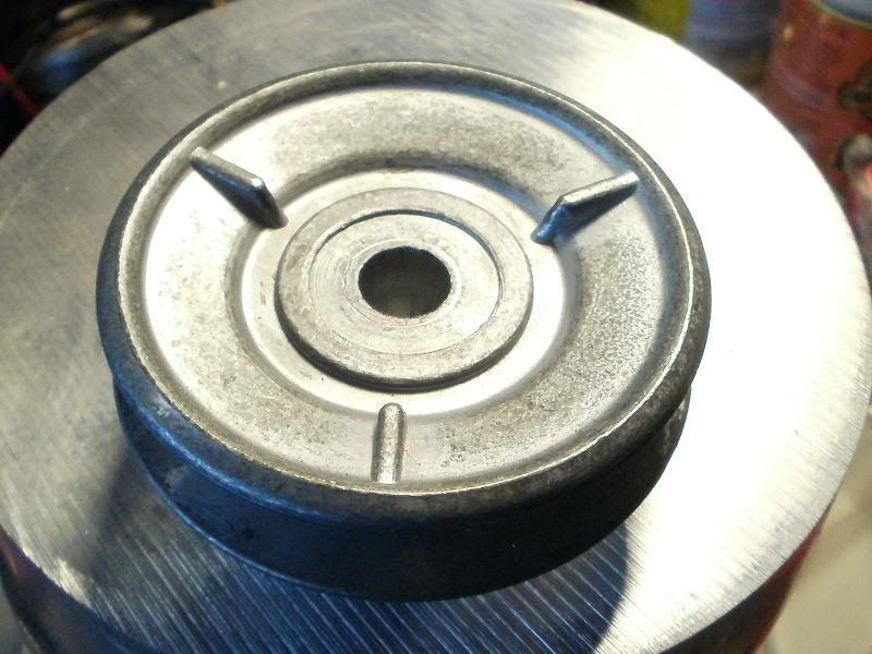
                              • I redirect our attention back to the photo of the backside/rotor side of the pulley!


                                It's recessed/concave in a couple of places as you can see by the rings around the center, and the entire surface of the side of the pulley out to the edge. The central hub of the Rotor is just slightly recessed from the actual surface of the outside ring of the Rotor, so a spacer or washer(s) should be found that would fill in the depth of the recesses of both the Rotor's central hub and the pulley, so that the outer edge of the pulley could be braced against a large plate that would make contact all the way around the outer ring of the Rotor.

                                This plate would be the section that would be cut out of the 1/4" thick mounting plate..the section where the rotor sticks out thru the plate, and so would just require central drilling of that plate, and then positioning between the Rotor and pulley, then the outer edge of the pulley would be pressed against this plate reducing or possibly eliminating any FLEXING stress on the bolt, since the flexing stress of the pulley would be exerted against it's outer edge and against the large plate against the rotor!?!?

                                Does this sound like a plausible/possible solution to reduce the flexing tendency of the bolt, so it would have mostly just direct head pressure holding the pulley/plate/washer/rotor against/onto the crank???

                                T.C.
                                T. C. Gresham
                                81SH "Godzilla" . . .1179cc super-rat.
                                79SF "The Teacher" . . .basket case!
                                History shows again and again,
                                How nature points out the folly of men!

                                Comment

                                Working...
                                X