Godzilla Resurrection: Re-build thread

Collapse
X
 
  • Time
  • Show
Clear All
new posts

  • motoman
    replied
    Originally posted by TopCatGr58
    Now you tell me after all of my major welding is done!

    So you're saying to backtrack on the weld seam I just created at the end...kinda like when sewing to backtrack to LOCK the stitch! Are you saying the extra filler/heat helps to release the tightening stress that would normally be there at the end of the bead??

    Hey Skids, I'll be monitoring it to see how it holds up!

    T.C.
    Sorry bout' that T.C..........guess just assumed anyone who has welded a bit already knew that...........and kinda sorta' what your sayin', but mostly just ending the weld leaves a bit of a crater, which I've seen become the weak place for a fracture to start. This type of application related to any stress, which is minimal anyways, imagine your gusset welds should be just fine. I used to see this more often associated with loader bucket bottoms and other heavy equipment applications........know our XS's are a bit heavy, but would likely never see that kind of stress as the frames are already stress relieved by design and existing cross pieces. BTW, same goes for meeting of two welds(need new rod to continue)... Welds should overlap each other, and not just end butted to each other.
    Last edited by motoman; 07-03-2016, 11:25 PM.

    Leave a comment:


  • TopCatGr58
    replied
    Weekend Update

    Okay, as I stated in my previous post, have done some more frame welding/reinforcing! Don't pay any attention to the RUST, I've already wire brushed it off, and threw a quick dose of that Rust converter primer on it!

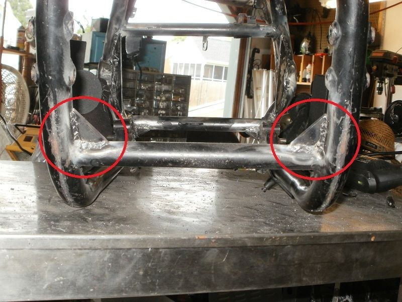
    Lower Front of frame

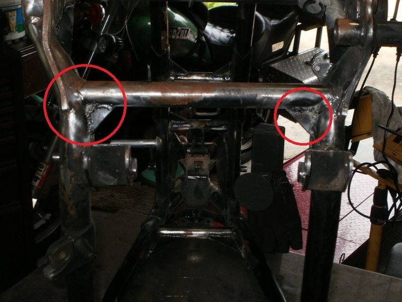
    Bottom rear of frame.

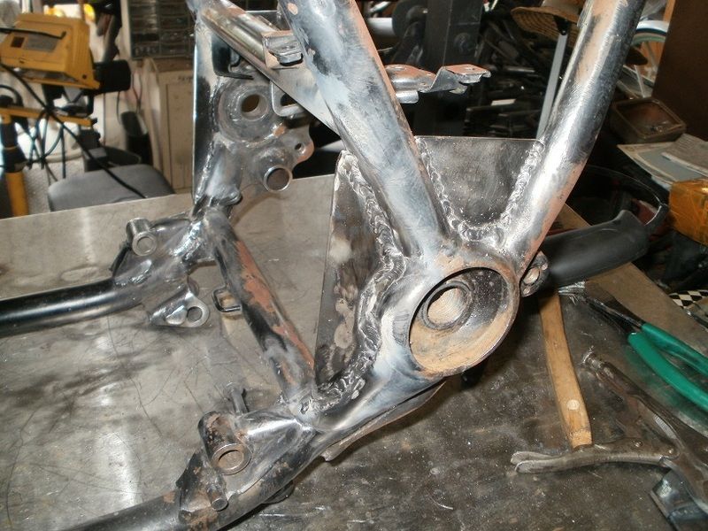
    The leading edge of the swing arm openings/joints.


    Looks like I'll be doing some more aluminum welding, as well as fixing the CENTRATION of the crank pulley for my ALT! Note the stress fracture of the bracket. Fortunately the newer beefier COVER I made helped to stabilize it.
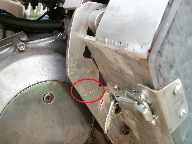
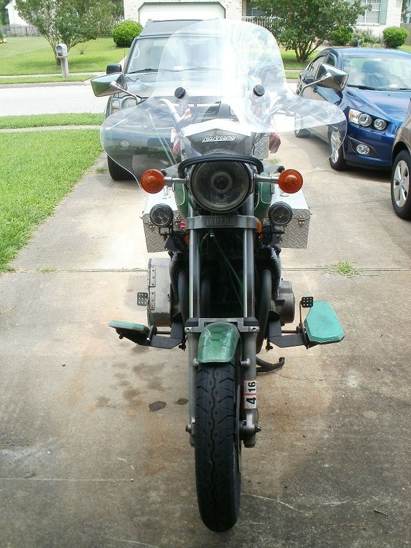
    I didn't get the crank pulley EXACTLY centered on the Crank Rotor, and so it had a "slight" vibration that caused the mounting bracket to flex too much and eventually cracked it completely through!


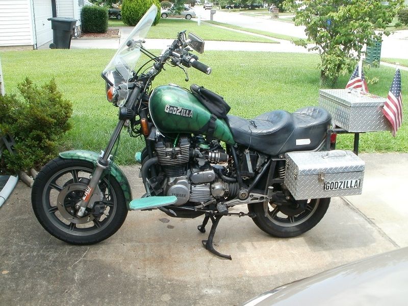
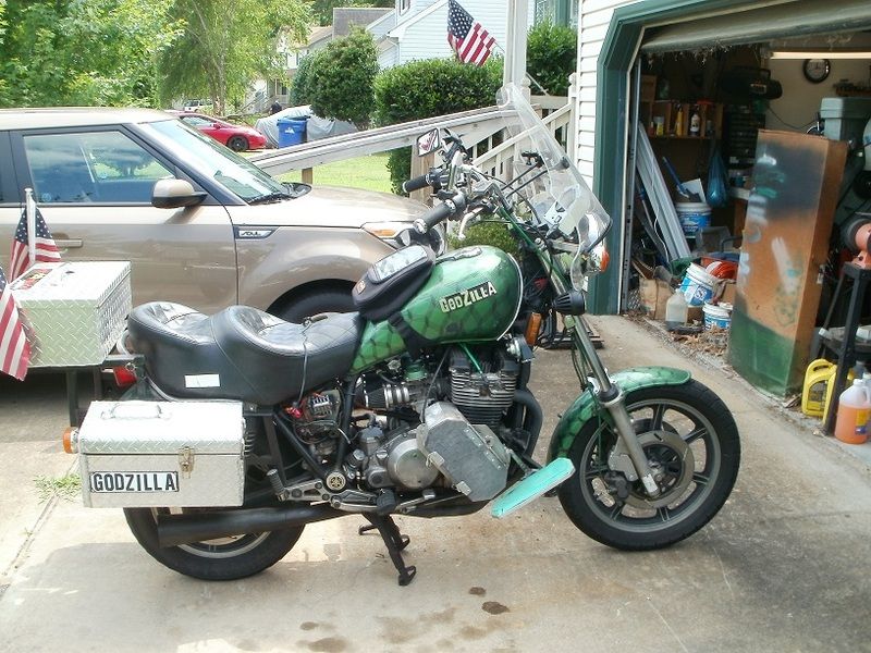
    Okay, these are the BEFORE photos everybody likes to be able to see! The engine paint is faded, as well as the wheel/rotor paint, gas tank, etc!


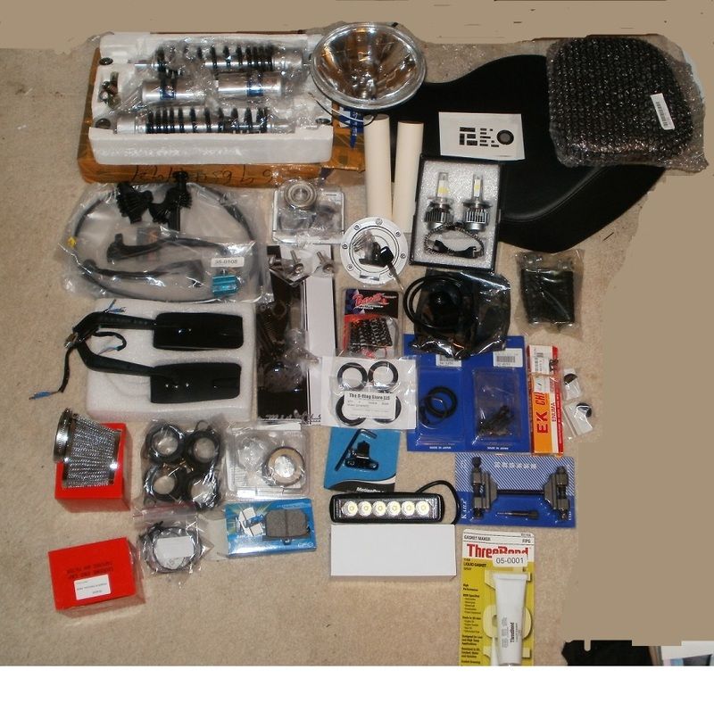
    Now to show you that I've been doing some SHOPPING in preparation for this project!


    New rear gas shocks, headlight reflector and HI POWER LED bulbs, Harley Seat, backrest, Polyurethane cylinders to make into engine mounts bushings,
    New controls decals/stickers, throttle/clutch cables/luber, rubber lever covers, clutch/brake levers, wheel bearings, gas cap-tank not shown, tire valves, petcocks, Barnett Springs, Aux Handlebar switches, Virago pedals, LED mirrors/turn signals, crankshaft seals, rear caliper and MC rebuild kits, cam chain/link, Valve cover halfmoons, Oval Pod Filters, Intake Boots, clamps, Motion Pro Valve tool, Cam chain tool, steering neck bearings/seals, rear brake pads/hardware, LED aux light bars x 2, and of course ThreeBond.
    There's more I'll be getting like SS bolts/nuts/washers and such.


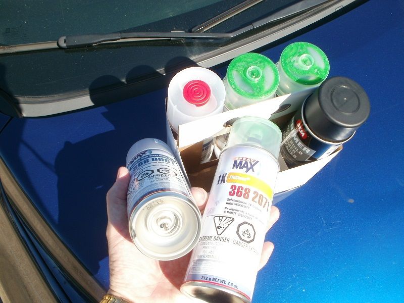
    And here's the PAINT....3 cans of the Synergy Green, buildable primer, 2 cans of CLEAR....note the mixing pin on the bottom!


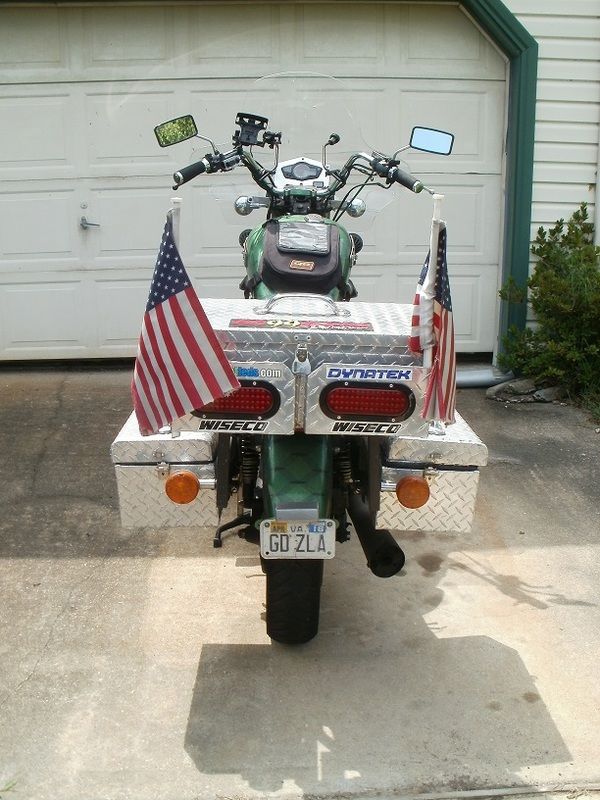
    Aside from the frame work, I started taking Godzilla apart, removed the trunk, saddlebags....found one of the slots for the bags mount was also cracked! Removed Seat, Fender, drained tank and removed, also the bags/trunk mounting hardware frame....that must have weighed ~10lbs alone! Also pulled battery...on tender!

    That's all for now!
    T.C.

    Leave a comment:


  • TopCatGr58
    replied
    Originally posted by motoman
    Just some advice: where you stop the weld bead, you should come back on your bead where it stops, before YOU stop the weld.
    Now you tell me after all of my major welding is done!

    So you're saying to backtrack on the weld seam I just created at the end...kinda like when sewing to backtrack to LOCK the stitch! Are you saying the extra filler/heat helps to release the tightening stress that would normally be there at the end of the bead??

    Hey Skids, I'll be monitoring it to see how it holds up!

    T.C.

    Leave a comment:


  • motoman
    replied
    Originally posted by skids
    TC, Do inspect periodically. Even the factory welds can eventually cause tubing cracks where the welding beads stop. I think that welding can make it less amenable for repeated stresses (more prone there for metal fatigue) -- but hey, I am no expert!
    .
    Just some advice: where you stop the weld bead, you should come back on your bead where it stops, before YOU stop the weld.

    Leave a comment:


  • skids
    replied
    Originally posted by TopCatGr58
    Hey there guys,
    TC, Do inspect periodically. Even the factory welds can eventually cause tubing cracks where the welding beads stop. I think that welding can make it less amenable for repeated stresses (more prone there for metal fatigue) -- but hey, I am no expert!
    .

    Leave a comment:


  • TopCatGr58
    replied
    Hey Ron,

    I remember doing some "NET" research a while back about stresses in sections that look like H/I beams and that most of the stress was along the joint/junction, and that putting holes in the plates didn't weaken the overall strength of the plate and stiffness. I was doing this with regards to the SPOKES on our rims, but then someone chimed it about how little weight is lost from drilling a bunch of holes in the spokes, similar to the rotors as well .

    So...not sure if I'll bother with drilling a buch of holes in the larger plate sections? Because the bike is going to be a SINGLE seater, I've already lost some #200 lbs just by not having a passenger! I'm also going to be dropping some of the forward controls stuff, wasn't really used much, and that's also a fair amount of weight with the angle iron brackets and large foot plate/rests and such!?

    But I understand where you're coming from, and it would probably be okay to drill some large holes in the larger plate sections for weight reduction and access without significantly reducing the strength/stiffness of the added plates.

    Interesting point about the rust flakes INSIDE the frame tubes. I thought I was able to hear a little rattling when I repositioned the frame at times?? I'll probably be cutting off the ends of the fender rails/tubes because I HATE those large round portions that were for the turn signal mounts/rubbers that I won't be using. So...that should provide some access to a part of the frame tubing, don't think that will get me any access to the front portions. I'll be using some rust convertor/primer for the frame prior to the final coats, it's amazing how fast it flash rusts with just the humidity around here!

    T.C.

    Leave a comment:


  • ViperRon
    replied
    I'd be curious if there would be a large reduction in support if the supports you welded in were drilled creating a webbed support. I ask and would like the experts to chime if this would be appropriate. This may give better access to certain areas without reducing strength. I am not saying it has to be done because TC has reduced much of the need for access but it would reduce the added weight and allow access to some points covered creating a customized effect I have seen in other types of bracing. It would also create spray paint access to areas that are hard to get to now.
    Speaking of paint before you paint TC you may want to position the frame to where you can put cleaner in the tubes to loosen the scale of paint inside from heating and then spray some rust preventer. I had a cousin customize the frame on a 48 Harley he had making a chopper out of it and that is one point he overlooked and now after 10 years is having some rust threw in some tubes. Originally I imagine these frames were washed and dipped before painting.

    TC sorry to invade your thread with my ideas but looks like you covered many of the stress points in this and with the age of frames and the rust that must be in some now we all may be looking at doing this type of bracing. If all things are included it might make a good add in to the modifications page on XS11 site.

    Leave a comment:


  • TopCatGr58
    replied
    Hey Kurt,

    Thanks for the comments about the welding quality, I try!

    Well, the Yamaha engineers didn't do as good of a job on the frame as they could have, otherwise it wouldn't have wobbled so much during the racing sessions. I've also thought about the transference of stresses, and hopefully the shocks/springs will take up most of it. I know the modern bikes are made of ALUMINUM which isn't as pliable as steel, and doesn't take to being flexed as much, and so the stresses must be exerted into the parts that do move.....ie. the suspension.

    I think it was Brian(UK) that posted the image of the 5K7 sport frame, I thought the bracing that was done to it was factory additions where Yamaha had figured out how to reduce the frame flex. But if they were just customized changes, that's okay.

    I also found info about normalizing, but the position/fitment/tolerance requirements aren't any where near that critical compared to parts/machine stuff that needs +/- 0.001" kind of predictability. Also, I tried to make the braces balanced on both sides of the frame.

    I'm also going to be making my own engine mounts cushions out of some cylinders of PolyUrethane I ordered and received, my old ones are worn out and the engine really wobbles/rocks in the frame.

    Hey Greg you little devil,

    Yeah, I'll be adding/welding in/on some different mounting bolts for my high output coils to make it easier to put them in and access vs. the OEM mounts. I'm also going to be reducing the amount of electrical gizmos...like the Reserve lighting unit, light checker, have already done away with the Reg/Rect, so I won't really have much in/under the braces that I will have to access.... I hope! Stay Tuned.

    T.C.

    Leave a comment:


  • BA80
    replied
    Being the devil's advocate as I'm good at, that's going to make some things pretty doggone hard to get to if they need to be worked on.

    Leave a comment:


  • kboehringer
    replied
    Originally posted by TopCatGr58
    SNIP
    Disclaimer, I'm not a pro-welder like Brant, just a home schooled hobbyist!
    TC,
    Those are some pretty darn nice looking welds. Your welds are also VASTLY superior to mine. I have a guy in my maintenance shop that has a welding cert that can't TIG or MIG that well!

    Question #1: is one that probably only the Original Yamaha Engineer could answer: If the frame has a weak point(s) and those areas are significantly reinforced as you have done, has another "weak point" been created concentrating or transferring forces further up the frame rail or to some other "Weaker" point?
    Question #2: Normalizing that frame after all that welding? This is not something I know much about but I would think the frame would have been PRE-Heated prior to that amount of welding? Would re-heating the entire frame and then allowing it to cool down slowly be appropriate to this project?

    Kurt

    Leave a comment:


  • TopCatGr58
    replied
    Real Progress UPDATE: Frame Welding

    Hey there guys,

    Okay, just to show that I'm actually working on this thing, and not just blowing smoke, here are the photos of my progress in frame reinforcement/welding!

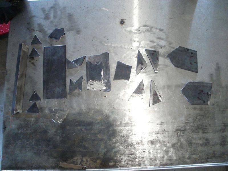
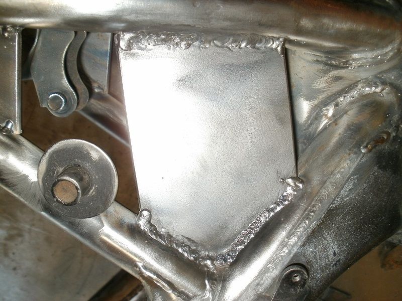
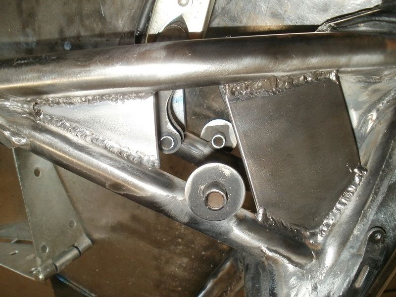
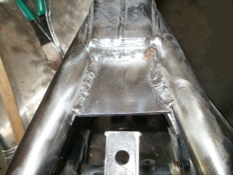
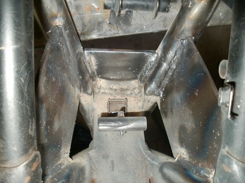
    These are the separate pieces that I had cut and shaped for fitting the frame locations.


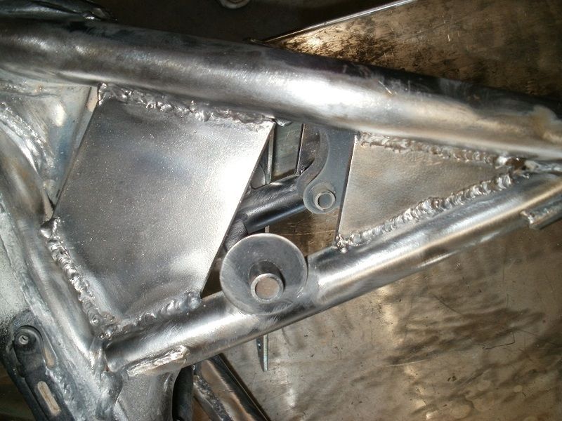
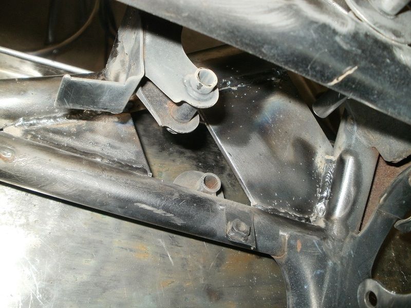
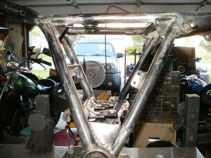
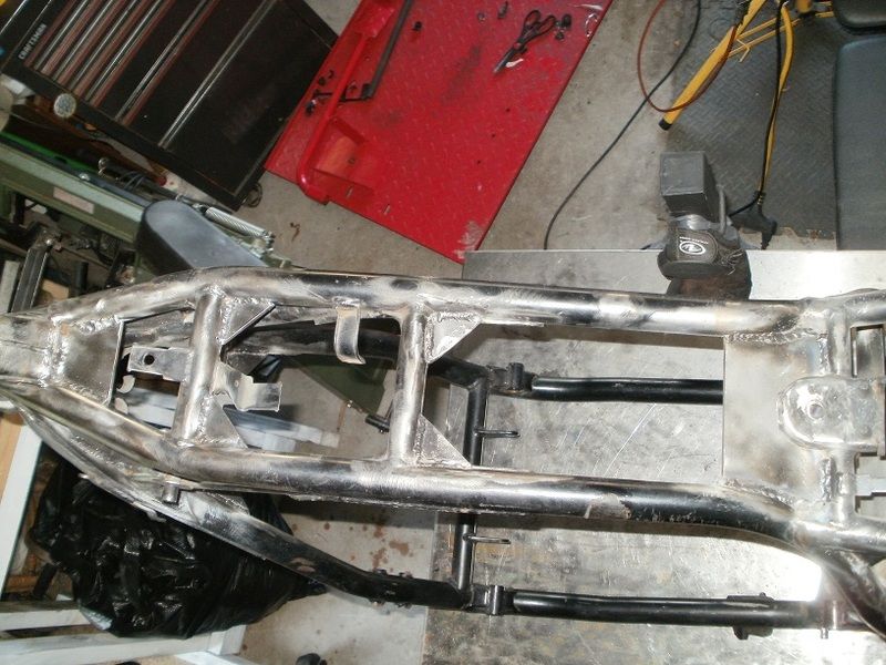
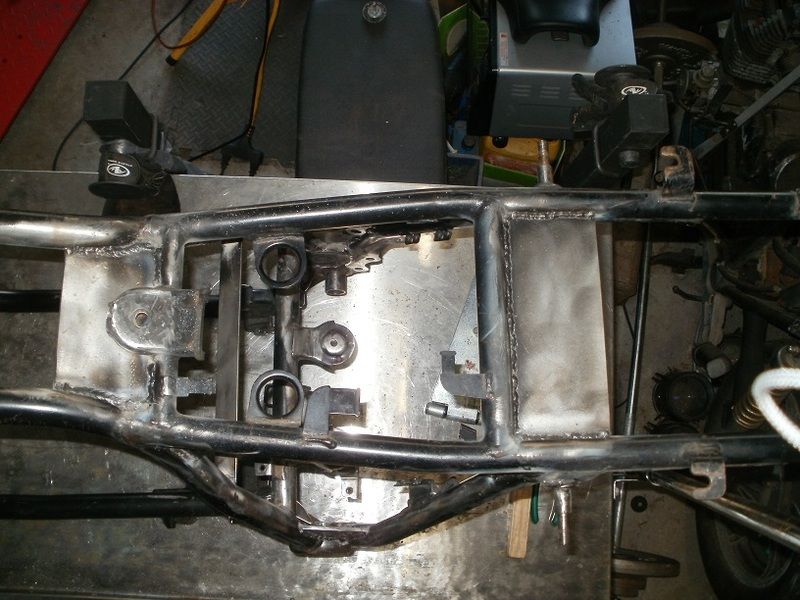
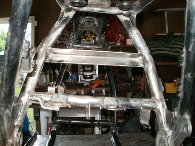
    I talked about this in the other Frame Reinforcement thread, but I'll reiterate it here. After doing a bunch of ONLINE research in weld stress relief with regards to different types of weld joints, butt, lap, tee, etc. and with the round frame tubing, I felt placing welds on both sides of the tee joint where the plate contacts the frame would be the best plan. The other images showed a very large piece of plate that essentially contacted the steering neck, upper and lower tubes all the way back to the junction. But the plate was lap welded to the frame.

    I decided to use thicker 3/16" plate, place them in the middle of the frame tubes between the tubes to allow me to apply welds to both sides of the plate. I may be wrong, we'll see later!? I also have a DC invertor Tig welder, big bottle of ARGON gas, lots of filler rod, so I thought I would first tack weld with my wire feeder, and then fill in the rest with the TIG to keep the slag down. These next few shots are of the front frame neck area where I did just that. The right I did first, got some porosity, did some more research, turned down my amps, cleaned my filler rod with brake cleaner, recleaned the metal surfaces with wire brush/drill, and verified that I was using the Tungsten Red tip, and put a smaller diameter cup on the tig handle.


    But after some success, I then attempted some other sections, and once again started experiencing porosity. I was also surprised at how LONG it takes to perform TIG welding! SO...I decided to just use the wire feeder, plus it was the only way to get to the inner sections of the plate weld seams.
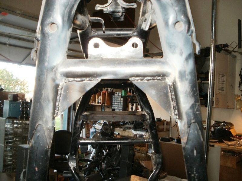


    Here's the side panel triangle space, please ignore the background crap, my garage is quite cluttered at the moment!


    Here are the top sections, note I removed the Reg/Rect mounts since I'm running my other mini race alt with built-in reg/rect.


    Here's the section under the seat/fender support rails.


    This the the section under the seat just in front of the battery compartment...finally found a place where I could use that Angle Iron Brant suggested! I felt this would provide decent stiffness/support without as much weight compared to a 3" wide solide plate section. I know it's not perfectly straight/level, but it won't be seen from this angle when the bike's all together.


    Okay, any comment, complaints, suggestions, etc.?

    Disclaimer, I'm not a pro-welder like Brant, just a home schooled hobbyist!

    T.C.

    PS, I'm not done with the frame, have a few more braces to place down low in the rear, and still deciding if I need/want the ones in FRONT of the swing arm pivot points!

    Leave a comment:


  • Radioguylogs
    replied
    Synergy Green and Black

    You're welcome.

    I hope to see it in September!

    Leave a comment:


  • madmax-im
    replied
    According to the XJ service manual...front forks get the minimum of 7 lbs PSI and a MAX. PSI of 17lbs "do not exceed"
    Out back the airshocks take... Minimum/Standard setting is 14 PSI and MAX PSI is 57 lbs
    TC going to love seeing that color...

    Leave a comment:


  • jwhughes3
    replied
    Originally posted by TopCatGr58
    Hey John,

    Swingarm photos are now up in that thread.

    Greg, new Air Shocks are on my shopping list. I'm running some slightly longer front spacers which put a little more preload tension on the springs, running Dextron III "fork" oil which is ~15 wt equivalent, am running an Elite III rear, IIRC, ChengShin 110/90-19 front.

    I'm working on the testicular courage, gotta see my Doctor for my Testosterone shots for LOW-T !

    Thanks TC!

    I have the XJ Air shocks. I think they do make a difference but I don't have 40psi more like 25-30. I thought 40 psi might kill me

    On our last Colorado ride last year I think I proved Greg's theory. All my curve squirrelliness went away after I put two new tires on in Grand Junction (front) and Durango (rear). Night and Day. The front was showing a small amount of cupping by the time I got to Colorado. None on the rear. But the "wallowing " feel in high speed long curves went away completely. It was hard to follow Brant in the curves without pulling at least 70-80 in those sweepers.

    John

    Leave a comment:


  • TopCatGr58
    replied
    Just reposting this for affect, thanks RadioGuy!


    I just ordered my paint from my local auto paint shop. I'm going the EASY way and having them mix up 3-8oz rattle cans of the Synergy Metallic Green for me! They also have this nifty 2 part Clear/Hardener in a Rattle can but will have 24-48 hour shelf life once mixed to allow me to be able to spray, dry, wet sand, dry and respray in the hopes of being able to lay down multiple layers of clear to get that really nice deep gloss affect as well as enough layers of protection against the fuel!!! They also have this thick BLACK primer that is supposed to build up fairly well and then be sandable to get a better smoother layer for the base coat. The guy said that the black will cover better with the green than using Gray Primer!?

    Total was about $175.00, but will be easier than having to get out the HVLP sprayer IF it still works after storage for 10 years after my first "custom" paint job! The proof will be in the pudding when I finally get around to doing it, still have lots of other stuff to get done first. Will be tackling the frame bracing tomorrow, came home with $50.00 worth of 1" angle iron and 1/8" thick plate stock!

    Kurt, with the modified R6 recessed cap area, how would you suggest painting it to prevent the possible penetration of fuel under the paint? Thinking about leaving an area around the spout paint free, then laying down the clear that would go beyond the edge of the paint up to the spout since it will have the hardener it should provide a seal/protective layer zone so the fuel won't be able to get to the base metal or under the paint!?

    T.C.

    Leave a comment:

Working...