
 Tweet
Tweet
A while back I swapped out my stock front MC for an aftermarket one with a bigger bore as I delinked my braking system and thought it might be wise to push more fluid now that the MC was working both front calipers. This resulted in 2 minor annoyances...the right side mirror mounts at a different angle from the left side (bugs me every time I look at it ) and there is no wiring for the low brake fluid sensor that is stock on the XJ so the "Brake" warning on the dash is on all the time. The original MC isn't usable so I found one on Ebay, got it all hooked up and bled the system so now the mirror looks right but the warning is still on. Here is what is inside the MC --
[IMG]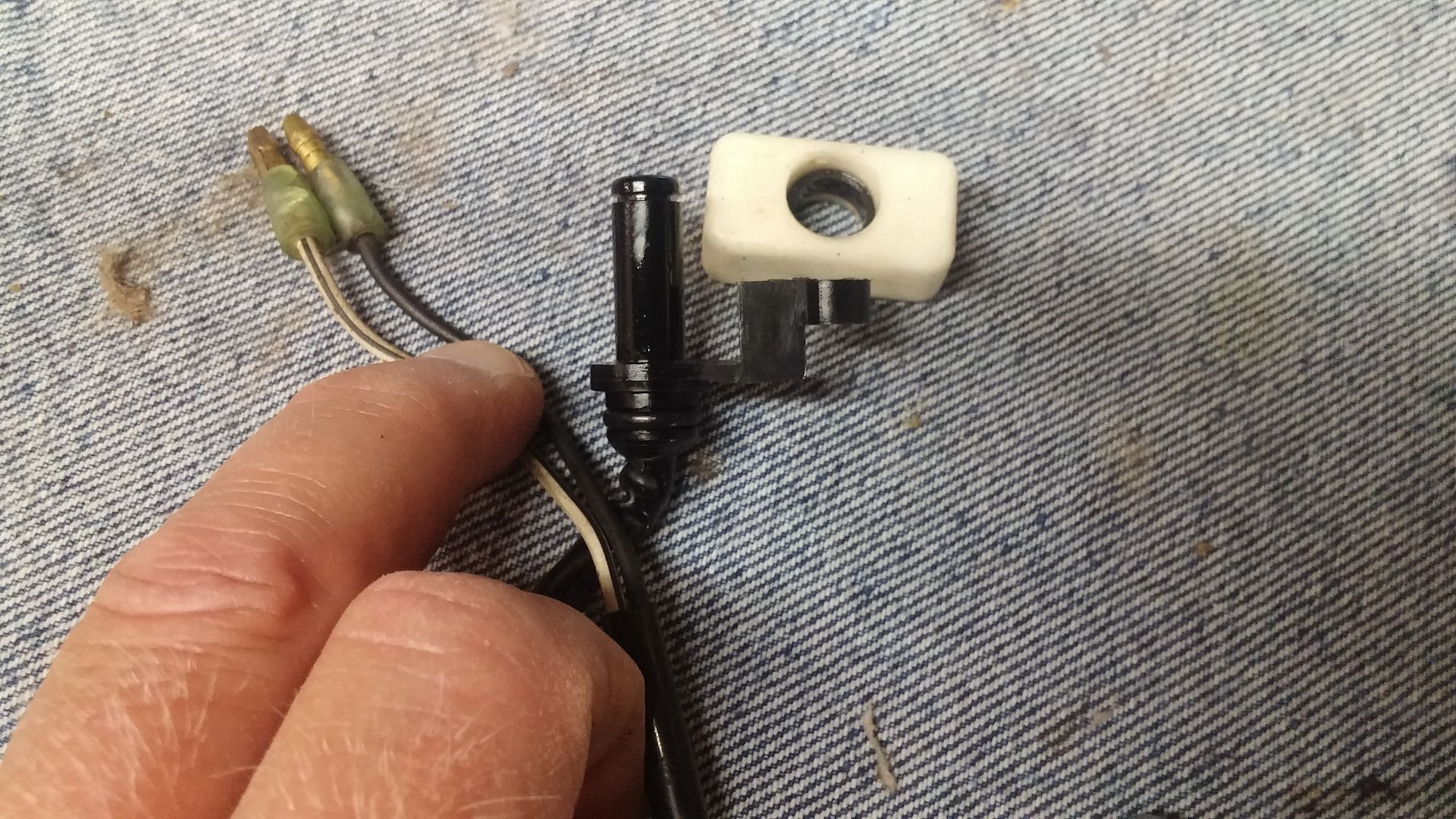 [/IMG]
The post goes up through the bottom of the MC reservoir and the o-ring seals it. A screw goes through the little "foot" on the right and is threaded into the bottom of the reservoir inside of it. Then we have the rectangular styrofoam float with a little "donut" magnet in the middle of it that slides over the post, it is held on the post by an E clip fastened to the top of the post. So knowing very little about electricity I start fumbling around. Here is what I get when checking continuity with the float at the bottom of the post (which would mean fluid level is low)--
[IMG]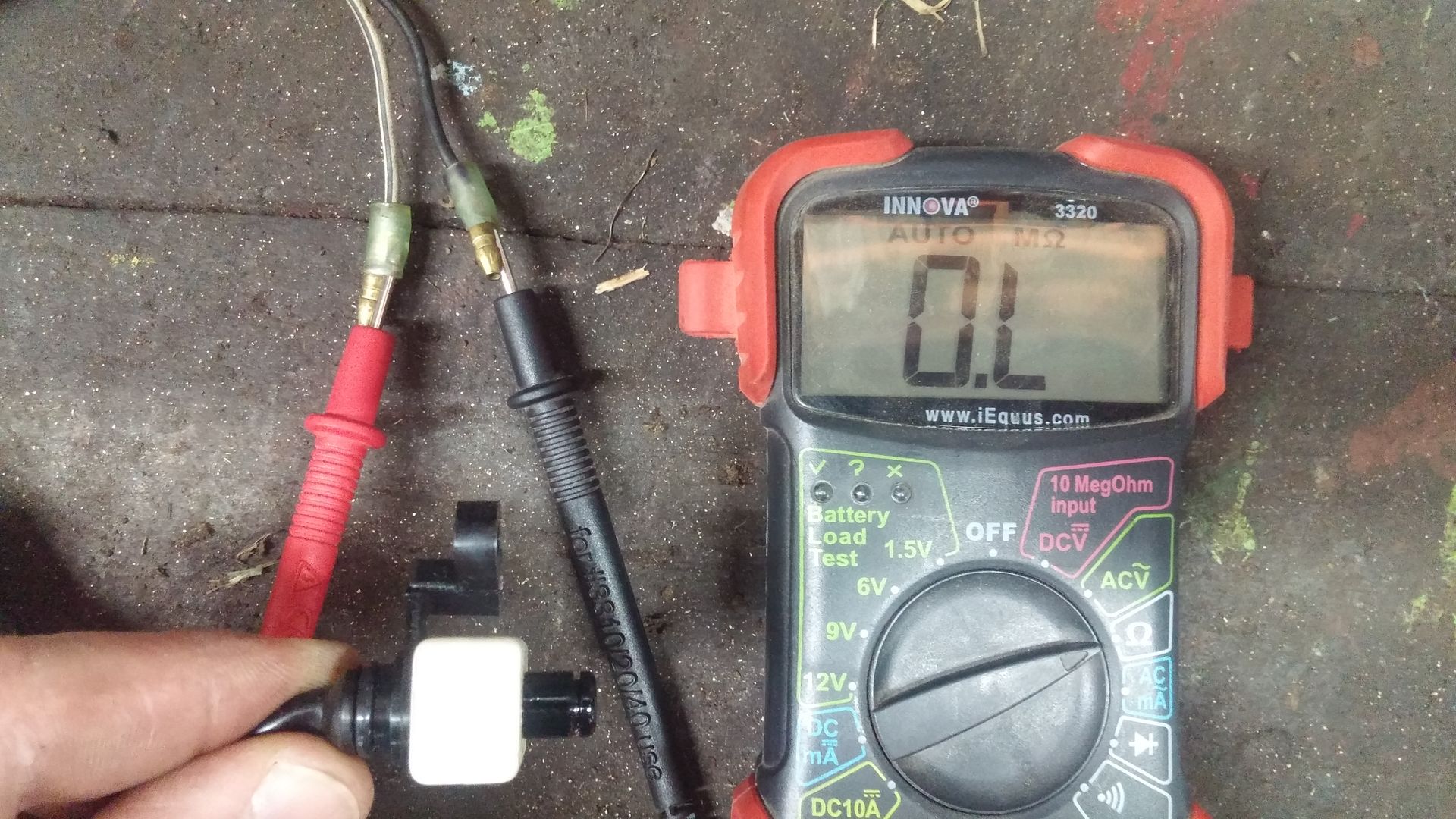 [/IMG]
And this is what I get when the float is at the top of the post, indicating the fluid level in the reservoir is full--(can't get PhotoBucket to turn the pic right side up )
)
[IMG]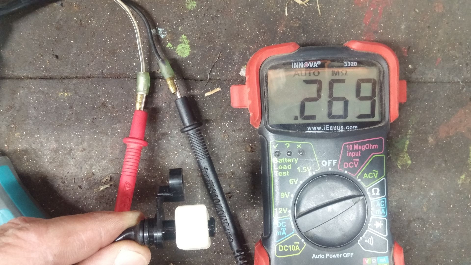 [/IMG]
Does all this mean the circuit is open when the level is low and there is no continuity? And the circuit is complete when the level is full and we have a tiny bit of resistance registering? How can the fluid warning be on when the level is low if the circuit in not complete? Any insight you can give me to help remedy this is greatly appreciated, thanks.
) and there is no wiring for the low brake fluid sensor that is stock on the XJ so the "Brake" warning on the dash is on all the time. The original MC isn't usable so I found one on Ebay, got it all hooked up and bled the system so now the mirror looks right but the warning is still on. Here is what is inside the MC --[IMG]
 [/IMG]
The post goes up through the bottom of the MC reservoir and the o-ring seals it. A screw goes through the little "foot" on the right and is threaded into the bottom of the reservoir inside of it. Then we have the rectangular styrofoam float with a little "donut" magnet in the middle of it that slides over the post, it is held on the post by an E clip fastened to the top of the post. So knowing very little about electricity I start fumbling around. Here is what I get when checking continuity with the float at the bottom of the post (which would mean fluid level is low)--
[IMG]
 [/IMG]
 And this is what I get when the float is at the top of the post, indicating the fluid level in the reservoir is full--(can't get PhotoBucket to turn the pic right side up
)[IMG]
 [/IMG]
Does all this mean the circuit is open when the level is low and there is no continuity? And the circuit is complete when the level is full and we have a tiny bit of resistance registering? How can the fluid warning be on when the level is low if the circuit in not complete? Any insight you can give me to help remedy this is greatly appreciated, thanks.
 So if the sensor was working properly and the reservoir was full, there would be zero resistance and the circuit would be closed and the warning goes out? I'll try connecting the 2 wires together that the sensor wires connect to and report back.
 ) sitting here and compare to my bike. Then it hits me. The rear MC sensor plugs into 2 White/Black wires just like the diagram shows. But on my bike when I delinked the braking system, I replaced the stock MC and proportioning valve with a MC from a '79 which of course has no sensor in it. I start rooting around and low and behold those 2 White/Black wires on my bike are just dangling there tucked away between the battery and the battery box
")
Comment