Announcement

Collapse
No announcement yet.

RPM measurement for carb sync

Collapse
X
 
  • Filter
  • Time
  • Show
Clear All
new posts

  • RPM measurement for carb sync

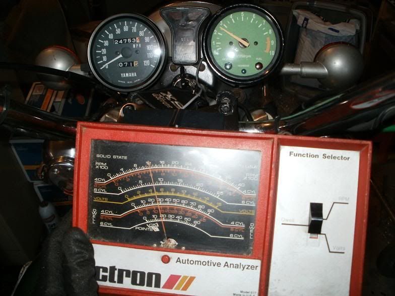
    I want to fine tune my four carburettors and found an Electrotest Speedograph MK2, suitable for 4 and 6 cylinder engines, made by Speedograph Ltd., Arnold, Nottingham England.
    Anyone knows if this instrument is suitable for the Yamaha XS11 and where to connect the two leads to?
    79 SF Canadian

  • #2
    Hey Ben,

    Okay, I did a search and found a few of those on eBay, here's a photo closeup of the gauge!


    They also had a photo of the manual, it says it has 2 ranges for the tach function...a HI-Tach and a Lo-Tach. Look at the top scales....one is range in 10, 20, 30 to 60 which is actually X's 100 for 2,000 , 3,000 etc. hi rpm range, and the scale just below that is marked in number 2, 4, 6, 8....12 which is also X's 100 for low rpm range 200 to 1200 using the Lo-tach mode.

    Here is a photo of my old Actron Dwell/tach/voltmeter that I used to check my Mini-Alt's charging as well as my oem tach function....I wired it using my mini-alt and wanted to be sure about what rpm I was checking it at.


    The gauge is for 4 cylinders, or 6 and 8 similar to your gauge. But mine doesn't have the Hi-Lo-tach function, just different scales for the different cylinders. The 4 cylinder mode(Top scale range on my gauges) was reading at 1/2 the actual speed, so it was reading ~1200 rpm, bike was actually at ~2500 rpm. See my OEM tach reading.

    Your gauge ranges have ie. 4000 and 800 aligned for the Hi- Lo- Tach modes, which are a factor of 5 difference. But this is just a scale/sensitivity difference, not a difference # of cylinders difference. Being in the 4 cylinder mode it will probably still read 1/2 of actual rpm, so using the LO-tach mode, it will probably read about 600 when you have the bike up to 1200 rpm, so it should still be usable, you'll just need to be aware of doubling the rpm on the scale no matter what mode you use to get the actual reading.

    Now, what I did was put a tap onto the Grey(-) wire for the spark plug coils, but I patched in at the TCI and ran a spare wire out from that that I could attach the gauge to. The Colored sensor wire/clip of the gauge connects to the (-) terminal of the Plug Coil, and the black wire/clip of the gauge will connect to engine/frame ground.

    Okay, hope this helps you get the most out of your gauge.

    T.C.
    T. C. Gresham
    81SH "Godzilla" . . .1179cc super-rat.
    79SF "The Teacher" . . .basket case!
    History shows again and again,
    How nature points out the folly of men!

    Comment


    • #3
      Thanks a lot.
      The only problem I have is locating the correct wire or terminal. I can perfectly find it on my 1952 VW Beetle, but not on a 'modern' engine like this.
      79 SF Canadian

      Comment


      • #4
        Ben,
        Connect Negative tach lead to either the Orange or Grey at the TCI connector, the Positive tach lead to Battery +. The XS will read one-half the RPM's you think it should. No matter, what you are looking for in the tuning process is HIGHEST rpm reading as you get closer to ideal tune.
        Former owner, but I have NO PARTS LEFT!

        Comment


        • #5
          Hey Randy,

          I know you're an electronics guru...but this gauge he has is quite old, very similar to my old Actron Dwell/tach/voltmeter. There is a small amount of voltage/power coming off of the (-) terminal....grey or orange wire at the TCI which seems to power the tach. I connect my (+) wire/alligator clip of my gauge to the Gray/Orange wire, and I just connect my (-) clip to engine/ frame ground. My gauge doesn't use or have a battery/power supply. It's powered all from the things it's measuring.

          The only time I connect it to the Battery's (+) terminal is when I want to measure the Volts of the battery/alternator.

          So...this is why I'm questioning your recommendation of connecting his test lead to the (+) battery terminal!?!?

          Ben, I would FIRST connect the colored/(+) meter test lead to a tap on the Grey/Orange wire at the TCI. Even though it is the (-) terminal....Electricity is actually flowing out of that (-) gray/orange wire. Then connect the (-) gauge test lead just to GROUND and see how the gauge behave....this way you aren't putting full strength 12 V Battery directly to it.

          T.C.
          T. C. Gresham
          81SH "Godzilla" . . .1179cc super-rat.
          79SF "The Teacher" . . .basket case!
          History shows again and again,
          How nature points out the folly of men!

          Comment


          • #6
            Actually, the orange and grey are the negative sides of the coils, just as in a car. remember, the red/white is the feed +12, then through the coil, then to the TCI which does the switching to ground.

            I only posted what works on my old-school tach / dwell meter. I have a Sun unit.
            Former owner, but I have NO PARTS LEFT!

            Comment


            • #7
              Originally posted by DAVINCI View Post
              Actually, the orange and grey are the negative sides of the coils, just as in a car. remember, the red/white is the feed +12, the through the coil, then to the TCI which does the switching to ground.

              I only posted what works on my old-school tach / dwell meter. I have a Sun unit.
              Right, that's essentially what I said, and now you're saying it the way I did. Your previous post sounds like you are saying to put the (+) Test lead onto the BATTERY (+), and the Meter (-) Test lead onto the Grey wire, that's what had me puzzled/concerned.

              But now you are saying it the way I said it....the Meter (+) test lead onto the gray wire, and the (-) Test Lead to ground!

              T.C.
              T. C. Gresham
              81SH "Godzilla" . . .1179cc super-rat.
              79SF "The Teacher" . . .basket case!
              History shows again and again,
              How nature points out the folly of men!

              Comment


              • #8
                Originally posted by TopCatGr58 View Post
                Right, that's essentially what I said, and now you're saying it the way I did. Your previous post sounds like you are saying to put the (+) Test lead onto the BATTERY (+), and the Meter (-) Test lead onto the Grey wire, that's what had me puzzled/concerned.

                But now you are saying it the way I said it....the Meter (+) test lead onto the gray wire, and the (-) Test Lead to ground!

                T.C.
                NO.

                The meter needs a positive source from the battery. That's the red lead. The black goes on the neg side of the coil. in our case that's either the orange or grey. Then, as the orange or grey swings low to high the meter converts that to RPM
                Former owner, but I have NO PARTS LEFT!

                Comment

                Working...
                X