Announcement

Collapse
No announcement yet.

Insulated Wire Crimps...

Collapse
X
 
  • Filter
  • Time
  • Show
Clear All
new posts

  • Insulated Wire Crimps...

    ... are still a bad idea. Those who have been around a while will remember this thread...http://www.xs11.com/forum/showthread...ighlight=crimp where we beat the subject to death. Good reading if you haven't seen it.

    Here's the proof...
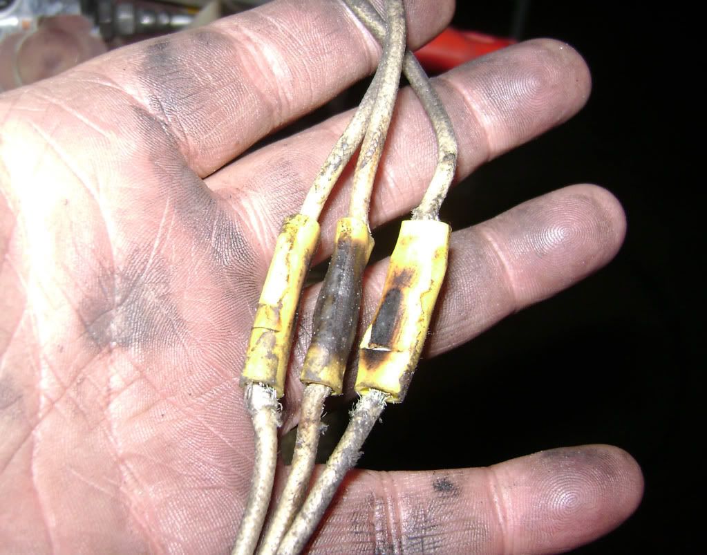


    Spliced into the stator leads from the alternator, these got a little hot....
    Fast, Cheap, Reliable... Pick any two

    '78E original owner - resto project
    '78E ???? owner - Modder project FJ forks, 4-piston calipers F/R, 160/80-16 rear tire
    '82 XJ rebuild project
    '80SG restified, red SOLD
    '79F parts...
    '81H more parts...

    Other current bikes:
    '93 XL1200 Anniversary Sportster 85RWHP
    '86 XL883/1200 Chopper
    '82 XL1000 w/1450cc Buell, Baker 6-speed, in-progress project
    Cage: '13 Mustang GT/CS with a few 'custom' touches
    Yep, can't leave nuthin' alone...

  • #2
    Steve, looks like a wally-world crimper and resistance had a fuzzy warm feeling..........but I still like the oil filter thread getting beat to death better...........myself, needs to go on a LD ride on my ST after replacing coolant elbows and o-rings..........makes doing the tranny fix on an XS look like a walk in the park. With the irrrelavent rheteric filter, oil, tire thing, makes me wonder if some others could use a LD ride also.......just an observation........ride safe all!
    81H Venturer1100 "The Bentley" (on steroids) 97 Yamaha YZ250(age reducer) 92 Honda ST1100 "Twisty"(touring rocket) Age is relative to the number of seconds counted 'airing' out an 85ft. table-top.

    Comment


    • #3
      Originally posted by crazy steve View Post
      ... are still a bad idea. Those who have been around a while will remember this thread...http://www.xs11.com/forum/showthread...ighlight=crimp where we beat the subject to death. Good reading if you haven't seen it.

      Here's the proof...


      Spliced into the stator leads from the alternator, these got a little hot....
      I cut the insulator off, flux, crimp, solder, and heatshrink. Some will argue that the wire will break behind the solder joint and I'm not here to argue theory but I have NEVER had a soldered joint fail but I've seen a lot of failed crimp-ons. I've made wiring harnesses for 6 or 7 tractors, installed a HD fairing on my Honda with a full gauge set, built a trailer from scratch, etc and I never have connection problems. I have a friend who uses twistlocs on his bike, his led wiring smoked a week ago
      Last edited by WSL91; 06-26-2012, 07:15 PM.
      1970? Honda Z50... gone
      1974? Yamaha 100 Enduro... gone
      1974 Honda CB200... gone
      1981 Yamaha Virago 750... gone
      1993 Honda Shadow 1100... gone
      2008 Honda VTX 1800F
      1982 Yamaha XJ1100J w/850 final, Raptor ACCT
      1979 Yamaha XS1100SF "Chewey" Raptor ACCT

      http://www.johnsoldiron.com

      Comment


      • #4
        I was a radio repairman in the Marines. We soldered everything to aerospace specs. The secrets to keeping a splice from breaking are as follows:
        1. Make an inline splice, not a parallel splice. A parallel splice is like when you use a wire nut. To do an inline splice make an X with the wires and leave a little more length at the bottom of the X. That way when you twist the wires you will have an untwisted space to attach your heatsinks. If you put a heatsink on a doubled up wire it will probably still wick up the insulation. I twist the tops of the X in oppisite directions because that's easier for me and it's the way I was taught.
        2. Use heatsinks to keep the solder from wicking up inside the insulation. A pair of hemostats (basicly locking pliers- try small needle nose pliers and rubber bands if you don't wan't to buy a set) will keep the solder at the repair. Once solder gets under the insulation bad things happen. Insulation flexes less than the wire and it will eventually fatigue and fail if solder gets under there.
        3. Finish off with heat shrink tubing (adhesive type if you can get it). Do yourself a favor and use a heat gun, not a lighter. You want to shrink the tubing, not burn it. One little bubble from overheating on either the insulation or heat shrink and you have to start over.

        Other soldering tips: Clean everything with alcohol before and after soldering. Flux will corrode the connection if you leave it on there. Speaking of flux, use it. It aids the heat transfer. Keep a damp sponge and clean the tip of your iron before each use. Put the iron on one side and the solder on the other and wait for it to do the work. The heat will pull the solder through the wire. If you touch the solder to the iron you probably won't have any solder in the middle of the connection. You should be able to see the strands of the wire when you are done. Too much solder dosen't help the connection and it looks like crap. When you get done soldering leave a blob on the end of your iron to protect the tip from oxidation. As a bonus you'll know when the iron is hot enough the next time because the blob will fall off. Wash your hands after soldering. Flux can give you diarrhea.
        80 G, Spaghetti pipes, K&N in stock airbox, Galfer S/S lines.

        It has been my experience that folks who have no vices have very few virtues. -Abraham Lincoln

        http://80xselevenrebuild.blogspot.com/

        Comment


        • #5
          +1 BobBaldy on how to solder but remember the military schools we went threw were much more strict than the technical schools most went threw. I was in the Navy so probably went threw the same schools you went threw. Doing labs they had specific procedure on how to to do each step and if you could not complete each little step exact it was all wrong. If you do a splice connection of wire it becomes stronger than original wire. These quick crimp connectors do not even allow you to see what you have done and lure people into a false sense that anyone can connect wire with no knowledge of what to look for.

          Most times the wire is damaged in the point of stripping clear wire and is doomed before they even start.
          To fix the problem one should not make more assumptions than the minimum needed.

          Rodan
          https://www.youtube.com/watch?v=khm6...liHntN91DHjHiS
          1980 G Silverbird
          Original Yamaha Fairfing and Bags
          1198 Overbore kit
          Grizzly 660 ACCT
          Barnett Clutch Springs
          R1 Clutch Fiber Plates
          122.5 Main Jets
          ACCT Mod
          Mac 4-2 Flare Tips
          Antivibe Bar ends
          Rear trunk add-on
          http://s1184.photobucket.com/albums/z329/viperron1/

          Comment


          • #6
            The Smoking Gun

            Steve,

            In the pic you hold the key to understanding the how and why I ( and the textbooks...) say that the "Western Union Telegraph Splice(soldered)" is 95% efficient.

            Obviously, those butt spices got hot enough to melt/burn. Yet I bet that even if anyone used a multimeter to check the resistance of those splices/connectors (when they were new...) the reading would have shown an extremely low Ohms reading. (.00000 something-or-other, right?) How could these "burn" when the resistance reading showed continuity and an almost perfect "dead-short" between the ends of the wire???? There's no way that Ohms law, Resistance, Voltage, Current, P.I.E. (Watts) or any of the math can esplain this.(According to the math it couldn't have happened...) Yet it DID happen as evidenced by what you found in front of your eyes. Something got HOT and burned/melted that plastic.


            The Answer:

            Hot equals heat. Heat and light are the same form of energy but at different wavelengths. Those connectors/splices took away some of the energy going through the wire itself and transfered it into LIGHT. (Infra-red... of course). That is something that you already know but the WAY you know it is about to change: INCANDESCENCE.


            An ordinary incandescent bult will show very little resistance and appear as a dead-short when checked with an ordinary multimeter. Yet when enough voltage/current/power is applied the filament starts to incandesce. From that point on the very process of "lighting up" provides the resistance in the circuit. Suddenly it's no longer a "dead-short" but a wonderful provider of illumination through incandescense. A "good" light bulb will draw a small amount of current and provide a good amount of light. Remember that this isn't exactly a "linear" function where the bulb turns on instantly and then the more power it gets, the brighter it gets. It only becomes linear AFTER the filament reaches that magic moment and actually lights up.


            Splices and connectors are nothing less than extremely bad light bulbs. They pass a LOT of current and provide very little light (and in the wrong wavelength for our eyes to see...). That is until that magic point of "incandescence" is reached. Then they put out a LOT of light/heat and magically provide a choke point as far as resistance/current flow is concerned. Before that point is reached, this filament/splice/butt connector still apears as a dead short with little reistance.

            The Westen Union Telegraph Splice/Tie (soldered) allows 95% of the wire's maximum rated current capacity to pass through with very little restriction. Past 95% though, the splice (which resembles a filament in a light bulb any ways...) acts to convert any more power into light/heat. That is until the splice (now turned into an incandescent light bulb filament) burns up/out.

            I wonder how many of the XS/XJ's would look like they were a christmas tree if viewed with a TIC. (Thermal Imaging Camera). I was a firefighter and we used one a LOT to find hot spots after we'd put out a blaze. We also used it whenever we responded to a "smoke reported" call. Usually it was the wiring behind the walls glowing/hot due to overloading or bad connections.


            I offer this now because in the original threads where I stated this "standard" 100% of the other contributors convinced themselves that this 95% efficiency/5% loss wasn't and COULDN'T be true. They "followed the laws/mathematics" and ended up digging a proverbial hole for themselves. It's been quite some time now and this post should serve to correct a fundamental error in their understanding of how our electrical systems work in the real world. It also robbed them of the "Aha!!!!" moment where they figured this out for themselves.

            Sorry 'bout that but then again: It's all about the bike's well being as far as I'm concerned.

            I'd follow Ivan's method here:

            Mcintire twist joint+solder+glue-lined shrink tubing+ mechanically secured for vibration+ loomed for chafe protection.

            Comment


            • #7
              I'm still not a fan of soldering, for all the reasons I originally posted in the first thread.

              As to the resistance of those splices, I did check them... and they 'tested' fine. Points out the limitations of hand-held meters, eh?...
              Fast, Cheap, Reliable... Pick any two

              '78E original owner - resto project
              '78E ???? owner - Modder project FJ forks, 4-piston calipers F/R, 160/80-16 rear tire
              '82 XJ rebuild project
              '80SG restified, red SOLD
              '79F parts...
              '81H more parts...

              Other current bikes:
              '93 XL1200 Anniversary Sportster 85RWHP
              '86 XL883/1200 Chopper
              '82 XL1000 w/1450cc Buell, Baker 6-speed, in-progress project
              Cage: '13 Mustang GT/CS with a few 'custom' touches
              Yep, can't leave nuthin' alone...

              Comment


              • #8
                Originally posted by crazy steve View Post
                As to the resistance of those splices, I did check them... and they 'tested' fine. Points out the limitations of hand-held meters, eh?...

                Just tells me that you didn't use enough duct tape and baling wire... and maybe a zip-tie or 20.
                Try your hardest to be the kind of person your dog thinks you are.

                You can live to be 100, as long as you give up everything that would make you want to live to be 100!

                Current bikes:
                '06 Suzuki DR650
                *'82 XJ1100 with the 1179 kit. "Mad Maxim"
                '82 XJ1100 Completely stock fixer-upper
                '82 XJ1100 Bagger fixer-upper
                '82 XJ1100 Motor/frame and lots of boxes of parts
                '82 XJ1100 Parts bike
                '81 XS1100 Special
                '81 YZ250
                '80 XS850 Special
                '80 XR100
                *Crashed/Totalled, still own

                Comment


                • #9
                  Those were installed by the PO; he said he'd been having some charging issues, no wonder....
                  Fast, Cheap, Reliable... Pick any two

                  '78E original owner - resto project
                  '78E ???? owner - Modder project FJ forks, 4-piston calipers F/R, 160/80-16 rear tire
                  '82 XJ rebuild project
                  '80SG restified, red SOLD
                  '79F parts...
                  '81H more parts...

                  Other current bikes:
                  '93 XL1200 Anniversary Sportster 85RWHP
                  '86 XL883/1200 Chopper
                  '82 XL1000 w/1450cc Buell, Baker 6-speed, in-progress project
                  Cage: '13 Mustang GT/CS with a few 'custom' touches
                  Yep, can't leave nuthin' alone...

                  Comment


                  • #10
                    The problem is they are too big, he shoulda used the blue color ones.
                    2H7 (79) owned since '89
                    3H3 owned since '06

                    "If it ain't broke, modify it"

                    Comment


                    • #11
                      Originally posted by crazy steve View Post
                      I'm still not a fan of soldering, for all the reasons I originally posted in the first thread.

                      As to the resistance of those splices, I did check them... and they 'tested' fine. Points out the limitations of hand-held meters, eh?...
                      Well, no. It points out a basic law. You can have one strand making a path for you and you will measure no resistance.. Still not a good thing.. and when you put some voltage under a load through that one strand you will see some heat and probably see the wire melt. For that measurement it doesThent reallymatter what meter you use.. Thing is, you will find bad connections made both with crimps and solder connections.. The solder actually doesnt do much for the electrical connection.. It adds strength to the splice.. Good crimps and good crimp tools will produce just as good a connection as soldered connections.. Problems occur when you dont weather proof your splice or dont provide enough physical support for it if it is going to be moving around. If you use high quality crimps of the propper size, quality tools and prepare the splice properly, you will actually be better off much of the time using crimp connectors. The solder, agiain, is not for conduction as much as it is for strength. You rely on twisting the clean wires together (western union comes to mind) for electrical connection..

                      Just my two cents worth.. I worked for 30 years aboard ships reparing electroncs.. Didnt really like to come back to redo a job.. Especially if it was up on a 60 foot mast.. underway at sea..

                      Lee
                      (sparks)
                      79 SF

                      Comment


                      • #12
                        Another thing to remember is that there is a BIG difference between a cheap crimp connector and the double crimp connector as used in factory connectors and such. I too was military electronics trained and there we soldered EVERYTHING, but it was as said all done as mentioned AND always strain relieved to prevent the flexing that will cause the wire to break.

                        The factory style double crimp connectors are many times more efficient then the cheap stuff though, and for our uses, are close enough to the good solder connections and without the weaknesses you get from soldering that IF you can get that type of crimp connector and have the right type of crimper (and I do) I prefer that most of the time to soldering. That said, there are types of connections that I make that I prefer to solder, primarily because I need them to be very very small and efficient, with no room even for the western union type splice (which is the type of splice I too was taught to make in basic electronics).
                        Cy

                        1980 XS1100G (Brutus) w/81H Engine
                        Duplicolor Mirage Paint Job (Purple/Green)
                        Vetter Windjammer IV
                        Vetter hard bags & Trunk
                        OEM Luggage Rack
                        Jardine Spaghetti 4-2 exhaust system
                        Spade Fuse Box
                        Turn Signal Auto Cancel Mod
                        750 FD Mod
                        TC Spin on Oil Filter Adapter (temp removed)
                        XJ1100 Front Footpegs
                        XJ1100 Shocks

                        I was always taught to respect my elders, but it keeps getting harder to find one.

                        Comment

                        Working...
                        X