Announcement

Collapse
No announcement yet.

wiring trouble - no spark!

Collapse
X
 
  • Filter
  • Time
  • Show
Clear All
new posts

  • wiring trouble - no spark!

    This is my first post, so I want to say thanks to the mods for letting me aboard. I'm from Philly and I'm currently riding an xs650 hardtail, but I've got a cb550 cafe and a BMW r50/2 in the works for this spring (I'll have to sell the cb to pay for the beemer though )

    I'm also working on an '81 xs1100 midnight. It was running rough when we got it, but it was running. Now, however, we've got no spark.

    We cut up the wiring harness per the 2 chop wiring diagrams we saw here. The only difference between what we did and what other diagrams did was we cut out the handle bar switches (so no kill switch) and added a automotive style keyed starter switch (so instead of a start button completing the starter circuit by grounding, the ignition switch completes the starter circuit by providing power)

    I can’t figure out what we did wrong, but now that it’s all together, we don't get any spark. The starter turns over, but that’s it. We’re getting voltage to the coils but it’s weak (about 9v in one and about 4v in the other). We're using a fully charged new battery.

    I feel like we messed something up wiring wise (probably with the igniter box), but I can’t figure out what isn’t working. The ignition switch momentarily cuts power to everything but the ignition circuit when the bike cranks (so lights, horn, alternator, reg/rec) but I can’t see that being a problem.

    We’ll check connectors and test the individual components next, but I want to rule out our wiring first - especially since the bike fired before we tore it down. I did take a look at the pickup coils and they look brand new. I couldn’t see any broken wires, etc.

    If you wouldn't mind looking at the diagram and seeing if there are any obvious errors, it would be greatly appreciated!

    Here’s the diagram we made from the others we saw:
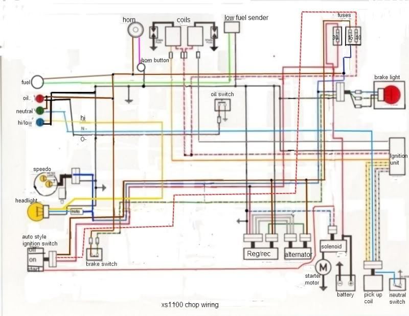

    http://i28.photobucket.com/albums/c2...100-chop-2.jpg

  • #2
    Originally posted by Lang View Post
    I did take a look at the pickup coils and they look brand new. I couldn’t see any broken wires, etc]
    Not that this is your problem, but 'looking' at those little wires IS decieving. With both hands pull on the insulation every inch. Those wires can and DO come apart inside! If that insulation stretches, there's a break internally.......Very common.....
    81H Venturer1100 "The Bentley" (on steroids) 97 Yamaha YZ250(age reducer) 92 Honda ST1100 "Twisty"(touring rocket) Age is relative to the number of seconds counted 'airing' out an 85ft. table-top.

    Comment


    • #3
      I don't see the resistor for the coils on your diagram, was it removed and different coils installed?

      If it's still on there the R/W wire from the solenoid should bypass it to provide full voltage to the coils during cranking.
      Greg

      Everybody is a genius. But if you judge a fish by its ability to climb a tree, it will live its whole life believing that it is stupid.”

      ― Albert Einstein

      80 SG Ol' Okie;79 engine & carbs w/pods, 45 pilots, 140 mains, Custom Mac 4 into 2 exhaust, ACCT,XS850 final drive,110/90/19 front tire,TKat fork brace, XS750 140 MPH speedometer, Vetter IV fairing, aftermarket hard bags and trunk, LG high back seat, XJ rear shocks.

      The list changes.

      Comment


      • #4
        motoman, duly noted. It looked so clean, I didn't pull on anything - but now I will. If the wires stretch, they're broken, right?

        BA80, the 81 didn't have a resistor (I think yami started using different coils) - although somebody should tell Clymers that because they still show it in the diagram (not that I'm surprised). So it's wired just like in the diagram and when I turn the key to start, power flows only to the solenoid and the coils/ignition unit.

        BTW, I was wrong, it's not a midnight, so no one get mad at me for chopping it up

        Comment


        • #5
          Originally posted by Lang View Post
          BA80, the 81 didn't have a resistor (I think yami started using different coils) -
          OOPS sorry, missed that when reading. But your right, the manual DOES show it.
          Last edited by BA80; 03-09-2012, 12:08 PM.
          Greg

          Everybody is a genius. But if you judge a fish by its ability to climb a tree, it will live its whole life believing that it is stupid.”

          ― Albert Einstein

          80 SG Ol' Okie;79 engine & carbs w/pods, 45 pilots, 140 mains, Custom Mac 4 into 2 exhaust, ACCT,XS850 final drive,110/90/19 front tire,TKat fork brace, XS750 140 MPH speedometer, Vetter IV fairing, aftermarket hard bags and trunk, LG high back seat, XJ rear shocks.

          The list changes.

          Comment


          • #6
            How about some pics?
            Keep the shiny side up
            1979 XS1100SF
            Mac 4-1
            Drilled airbox Uni filter
            Vmax bars
            Virago 1" shorter shocks
            30K miles
            http://i1228.photobucket.com/albums/...429_135845.jpg
            1981XS1100SH
            '80 G Forks and Triple Tree
            '80 G tank
            Mac Turnouts
            Virago 1" shorter rear shocks
            SH Headlight
            http://i1228.photobucket.com/albums/...psd6adaae1.jpg
            61 Wife
            83 Son
            86 Son
            89 Daughter

            Comment


            • #7
              Originally posted by Lang View Post
              motoman, duly noted. It looked so clean, I didn't pull on anything - but now I will. If the wires stretch, they're broken, right?
              Yup. If broke, refrain from soldering as the heat weakens the wire at that point. Us a non-insulated butt connector and cut it short to bout a 1/4", slip a short cut piece of shrink tubing gauged by color(pink) over wire and crimp connection then slipping the shrink tubing over repair. Eliminates the bulk and leaves wire flexible so vacuum advance rotates freely with out wire restriction.
              81H Venturer1100 "The Bentley" (on steroids) 97 Yamaha YZ250(age reducer) 92 Honda ST1100 "Twisty"(touring rocket) Age is relative to the number of seconds counted 'airing' out an 85ft. table-top.

              Comment


              • #8
                I don't see an actual power supply to the TCI in that diagram; the wire that comes out of the TCI and goes to the coils won't power up the box. It's confusing because Yamaha used the same wire colors in a couple of places and they don't do the same thing, so I'd check that. You should have a white/red at the box (to the coils, and it changes to red/white), and the red/white at the box is TCI power. The wire you now have tying to the coils from the fuse panel should be disconnected there and connected to the TCI.
                Last edited by crazy steve; 03-09-2012, 01:18 PM.
                Fast, Cheap, Reliable... Pick any two

                '78E original owner - resto project
                '78E ???? owner - Modder project FJ forks, 4-piston calipers F/R, 160/80-16 rear tire
                '82 XJ rebuild project
                '80SG restified, red SOLD
                '79F parts...
                '81H more parts...

                Other current bikes:
                '93 XL1200 Anniversary Sportster 85RWHP
                '86 XL883/1200 Chopper
                '82 XL1000 w/1450cc Buell, Baker 6-speed, in-progress project
                Cage: '13 Mustang GT/CS with a few 'custom' touches
                Yep, can't leave nuthin' alone...

                Comment


                • #9
                  Originally posted by crazy steve View Post
                  I don't see an actual power supply to the TCI in that diagram; the wire that comes out of the TCI and goes to the coils won't power up the box.
                  THere is, Steve.....it comes off the starter solenoid up to a fuse and from there to the TCI unit...
                  XS1100F 1980 European model. Standard. Dyna coils. Iridium plugs. XS750 final drive (sometimes). Micron fork brace. Progressive front springs. Geezer regulator/rectifier. Stainless 4 into 2 exhaust. Auto CCT (Venturer 1300) SOLD. New project now on the go. 1980 European model.

                  Comment


                  • #10
                    Steve, that was exactly the kind of thing I was thinking we might have done wrong but I'm still not seeing what I should be seeing. I was using these 2 diagrams:
                    http://www.xs11.com/forum/showpost.p...5&postcount=10
                    Both show it wired up the way I have it.

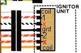
                    Here's a pic of an earlier ignitor. I know I can ditch the black/white wire and the 81 didn't have the red/yellow wire, and I know where the black, orange and gray wires go, so we're left with the 2 red/whites. It looked to me that those two wires are part of the same circuit, just going through the resistor, which I don't have, so I thought I should end up with one red/white. I'm not seeing a separate red/white for power to the TCI. Sorry I'm being so dense on this.


                    I wonder, is it possible that I don't have the red/white wire connected to the right spade on the ignitor? Do you happen to know which spade it should connect to?

                    Tweeleft, pics coming soon - but remember, it's got a long way to go

                    Again guys, thanks for your help.
                    Here's the full version of that full color diagram:
                    http://webpages.charter.net/kbhahn/xs11/E-Fwire.JPG

                    Comment


                    • #11
                      Originally posted by Lang View Post
                      ....I wonder, is it possible that I don't have the red/white wire connected to the right spade on the ignitor? Do you happen to know which spade it should connect to?
                      I think that's exactly your problem.... Now, I don't have a '81 harness here to check, but from what I know, with the ballast resistor missing from the factory harness you're lacking a 'tie' that would make your diagram work on an earlier harness.

                      Check at the TCI plug; you should have in the 'top' row a gray, white/red, black/white, and an empty space. The 'bottom' row should be a orange, red/yellow, red/white, and a black, all left-to-right looking at the side the wire goes in. If you check with the current wiring and the key on, you should find 12V on the white/red (and I'm assuming that's the color you find; you should still have 12V at that position) and no voltage at the red/white. This won't work. The white/red should go to the coils and your 12V switched supply, the red/white should be connected to your 12V switched source only; this is the actual power supply to the TCI.

                      I might be all wet, but I don't think so.... let us know if the above clears the problem.
                      Last edited by crazy steve; 03-09-2012, 03:56 PM. Reason: Oops; made a boo-boo...
                      Fast, Cheap, Reliable... Pick any two

                      '78E original owner - resto project
                      '78E ???? owner - Modder project FJ forks, 4-piston calipers F/R, 160/80-16 rear tire
                      '82 XJ rebuild project
                      '80SG restified, red SOLD
                      '79F parts...
                      '81H more parts...

                      Other current bikes:
                      '93 XL1200 Anniversary Sportster 85RWHP
                      '86 XL883/1200 Chopper
                      '82 XL1000 w/1450cc Buell, Baker 6-speed, in-progress project
                      Cage: '13 Mustang GT/CS with a few 'custom' touches
                      Yep, can't leave nuthin' alone...

                      Comment


                      • #12
                        To be clear: the TCI and the wiring harness are from the 81' so neither should have a provision for the resistor. I just used that ignitor diagram because I couldn't find one on line for an 80+ bike.

                        I will check the TCI plug connections next time I get a wack at the bike though (maybe this weekend - it's at my friend's house). And I will definitely post results.

                        I know I currently do not have a white/red wire. I only have a red/white one. Now when I removed the extra wires from the TCI harness, I pulled the connectors too, so I don't even have a little pigtail of wire sticking out to see what was there. I know I pulled the black/white one, but did I pull a white/red? Since Clymer's diagram is wrong and I can't find an 80+ diagram on line, I can't figure out what was on there.

                        But the question remains, I'm pretty sure people on this board have used those 2 chop wiring diagrams before - and the one red/white wire must have worked for them, so what am I doing wrong?

                        Comment


                        • #13
                          Steve, the more I think about this, the more I think I need to add back in a white/red to switched power - regardless of what the chop diagrams say.

                          Just to confirm, you think: red/white from switched power to TCI and coils and white/red from switched power to TCI. So that's 2 switched hots to the TCI.

                          red/white is on the bottom, 3rd from the left, white red is on the top, second from the left.

                          Comment


                          • #14
                            Where the confusion comes in I think is Yamaha apparently didn't change the number of wires going to the TCI when they revised the system to eliminate the ballast resistor. Looking at the circuit diagram in the unit repair section (again, this is for a pre-81 bike), the orange and gray are outputs to the coils, the black/white goes to the tipover switch (so can be eliminated), black is ground, red/yellow is the input from the starter solenoid (when closed to run the starter), that leaves the red/white and white/red. The red/white between the red/yellow and black is definitely the input power to the TCI.

                            Here's how I see it works; with just the key on, you have power to the red/white at the TCI, and the coils are fed through the ballast resistor, also with a red/white; there isn't a direct connection between these. While both of these wires are fed from the same place, they don't go to the same place. When you press the starter button, that applies power to the red/yellow back to the TCI, which then puts power to the white/red that also goes to the coils, supplying the full 12V instead of the reduced voltage coming through the ballast resistor.

                            So at the TCI you should only need the gray and orange wires (to the coils), the ground, and the red/white from a switched power supply. The other side of the coils can be fed by either t-connecting to the red/white going to the TCI, or by a separate wire connected to a switched power wire.
                            Fast, Cheap, Reliable... Pick any two

                            '78E original owner - resto project
                            '78E ???? owner - Modder project FJ forks, 4-piston calipers F/R, 160/80-16 rear tire
                            '82 XJ rebuild project
                            '80SG restified, red SOLD
                            '79F parts...
                            '81H more parts...

                            Other current bikes:
                            '93 XL1200 Anniversary Sportster 85RWHP
                            '86 XL883/1200 Chopper
                            '82 XL1000 w/1450cc Buell, Baker 6-speed, in-progress project
                            Cage: '13 Mustang GT/CS with a few 'custom' touches
                            Yep, can't leave nuthin' alone...

                            Comment


                            • #15
                              So, did we do it right then? We've got switched power going through a 10 amp fuse, then the wire splits, one going to the coils and the other to the red/white on the tci. then we've got the grey and orange wires going to the coils and black to ground.

                              If that's right, I guess it's time to check for crappy connections and if that fails, go component by component.

                              Steven and everyone else, thanks for your input. I'll make sure I'll post what ended up working (because something will work )

                              Comment

                              Working...
                              X