This is another tutorial for checking the electrical on your bike, and in this one I'll go over how to use your VOM (volt-ohm meter) and what to look for.
As any reader of this forum knows, these bikes are notorious for poor connections in their wiring. So, what constitutes a poor connection? How much resistance is 'too much'? So a few facts are in order...
The resistance of the wire is a non-factor; the smallest OEM size you'll find on these bikes (18 gauge) has a standard resistance of about 1 ohm per thousand feet, so a ten foot length would only be .01 ohm. This value is far smaller that you'll be able to measure with any hand-held meter, so for all practical matters it's the same as zero. And as size goes up, resistance goes down, so larger sizes will be even less.
So almost any problems you'll have will be where the wires are connected; either to another wire or to a component. The majority of connections are either a friction type, spring type (most light sockets), or a combination of the two (most plugs, switches). A few high-amp connections are bolted (battery, starter, main ground points and I'll have more on those later). As has been said many times, cleanliness is the main key here, as dirty connections don't conduct well, although loose connections can be just as bad. Ideally, the resistance through any connection should be zero but you won't get that, but you want to get as close to that as you can. So, what's a 'good' value?...
Right here I'm going to drag out a part of Ohm's Law to illustrate this; no, you don't need to know this, no math needed while checking the bike . But this will show just how much a little 'extra' resistance will affect your wiring for the worse. The formula I'm using is for calculating voltage drop across a resistance, any resistance, and it goes like this:
Vd = I x R
Where Vd is voltage dropped (or lost), I is current in the circuit, and R is the specific resistance, whether it's a component or a poor connection. So using this formula, let's do a couple of typical calculations that have direct bearing on our bikes. So for say a turn signal light, you have a .1 ohm 'extra' resistance in the circuit, caused by it's being dirty or loose somewhere. The lamp draws 2.25 amps, so: Vd = 2.25 x .1, or Vd = .225 volts. Not a lot you say, and you're right. But if this is in one of your connections for your charging system (where you can see current of up to 19 amps), now you're talking about a 1.9 volt loss (almost two volts) and that's enough that you won't charge your battery. Increase the resistance another tenth or two and you'll see problems on even the low current circuits. So moving on...
There's two ways to check circuits; 'cold' (no power) and 'hot' (powered up). Both ways have advantages/disadvantages, and sometimes you won't have a choice like when checking the alternator coils or ignition bits. One big advantage about checking cold is you have no worries about shorting anything out, blowing fuses or burning stuff up. It's also the method you'll probably have to use if the bike won't run or if checking the harness before running the bike. But one disadvantage to a 'cold' check is you're only applying a very, very small current to the circuit; once you put the circuit into use, the higher current can cause heating in a marginal connection and a higher resistance can show up. So even if a connection shows good 'cold', if you're still having issues you'll need to check it 'hot'. I'd particularly recommend checking the charging system output wiring hot once the bike is running.
So for cold checking, you need to know how low your meter will 'resolve' resistance, in other words how small a value it will measure. With a analog meter, it'll be tough to see a one or two tenth ohm value on the scale. Cheaper digital meters may not resolve well either, your better digital meters will be good down to a tenth. So the first thing to do is to see what the meter reads probe-to-probe (touching the two leads together).
[IMG]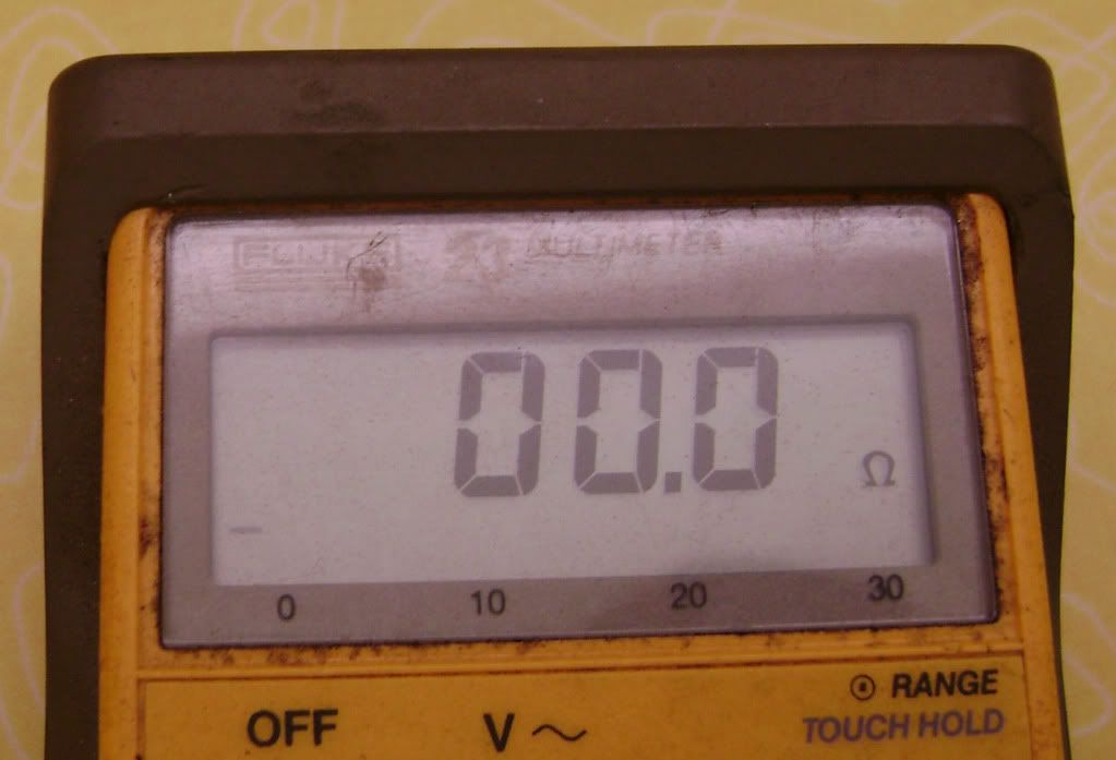 [/IMG]
My $100+ Fluke meter will 'zero out', so any reading above that is in the circuit. Note that most digital meters will take up to 15 seconds to zero out, so touch and hold until the reading stops changing. One advantage analog meters have is you can manually zero them, but again, seeing one or two tenth values on the meter face won't be easy.
[IMG]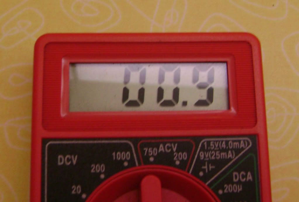 [/IMG]
The cheap HF meter won't zero out; this is the lowest it will read. All is not lost though; simply subtract this from your actual reading to get the circuit number. So if you see a value of 1.1 ohms, circuit resistance is .2.
So let's perform some actual 'cold' tests; turn your meter to 'ohms' (on it's smallest scale if a manual meter) and make sure your test leads are making a good contact connection, scraping to clean metal if you have to. If you have an auto-ranging meter, pay attention to what the display range is.
[IMG]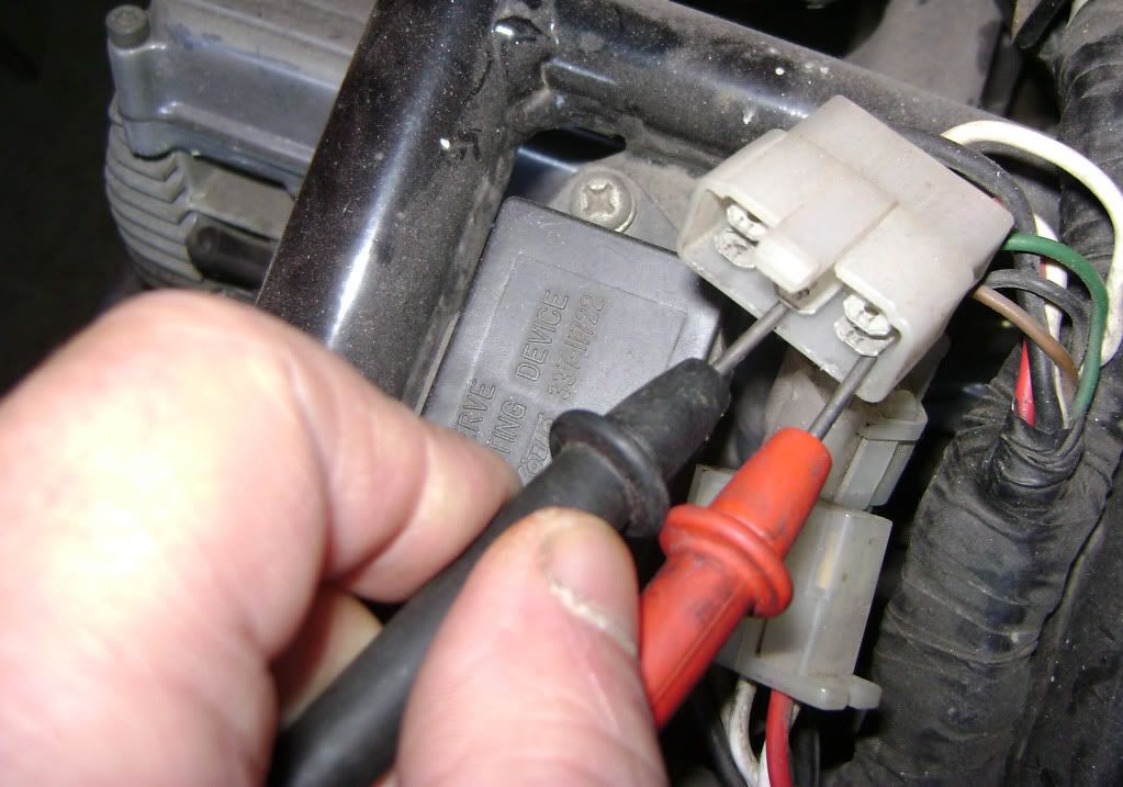 [/IMG]
Pic 1. Here I'm checking the alternator stator coil at the regulator. I'm looking for .4 ohm (+/- 10%) between the white wires. Now, seeing how the meter resolution is only .1 ohm, anything between .4 and .5 will have to be considered good. You should also check at the plug behind the fuse panel to make sure these plug connections are good. Same reading both places, the connections are good to go. You can do this same test on the pick-up coils at the TCI with the coils unplugged, get a good reading and you know the plug at the back of the motor is good. You can perform the same test for checking your handlebar switches by unplugging them from the main harness, just check between the appropiate wires.
[IMG]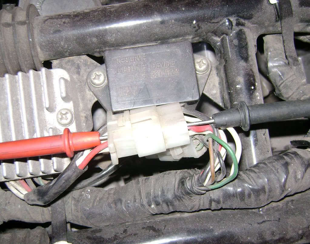 [/IMG]
Pic 2. Here I'm checking the actual internal plug connections; I've inserted the probes on both sides. This is very useful when checking a connection to a component. Get a reading above your zero amount, you have a loose/dirty connection that needs attention.
[IMG]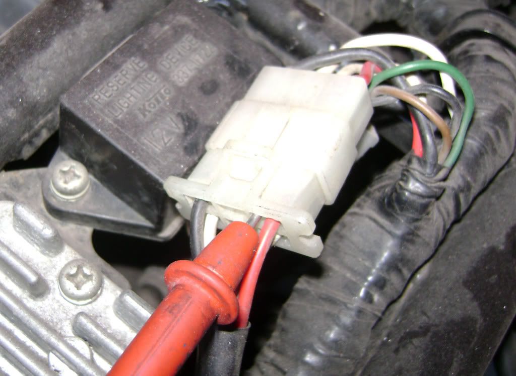 [/IMG]
Pic 3. Here's a test of the charging system output wiring; insert one probe at the regulator, put the other on the postive battery cable (where the other end of this wire goes). Again, any number above your zero amount means this needs attention. This is also a useful test for any other circuit positive or negative wire; simply put one lead on the wire to be tested and the other on the respective cable. If you get a 'bad' reading, then you'll have to start checking the various plugs and/or switches between these points to see where the problem is.
Ok, let's do some 'hot' checks. Turn on the bike, maybe start it for some tests. Set your meter for the lowest DC voltage range above 15 volts in a manual meter. Auto-range meters will read directly.
Connecting the leads as shown in pic 2 above, this will give a direct value for voltage loss in the connection. Zero volts would be great, between .1 and .2 volt is still decent, .3 volt or more you have a problem.
Connecting the leads as shown in pic 3 above, this will give you a point-to-point voltage loss reading. Going back to the positive battery cable hopefully will give the same readings as the above paragraph, but you may get a higher reading. I'd personally try for under .5 volt loss, less on higher current circuits like the charging system, ignition switch wiring, headlight, and ignition system supply for sure.
You can also use this method to check the ground half of the circuit; perform the above test, and note the amount. Subtract this from the system voltage (as measured at the battery). An example would be a .3 volt loss, 13.9 volts at the battery, which means you should have 13.6 volts at the test point. Check between the test point and your negative battery cable to verify this. Then check between your test point and the component ground point and see if it's the same. If it's lower, you have a poor connection in the ground half of the circuit.
I'll note here again that the 'main' ground connections on these aren't directly tied together (depending on paths through the frame), so checking between the negative battery cable and the other two ground connections (at the motor and regulator) for resistance is critical for proper system performance; any extra resistance between the cable and regulator ground connections will affect the whole electrical system. Check this 'cold' as shown in pic 3. I like to run an added #12 wire between these two points for added insurance.
You'll never get all the connections perfect, but this will help pinpoint just where your big problems are. Again, the high current systems will show the effects more than low current circuits will, but the better you get everything, the better things will work. This isn't as hard as it sounds, a novice who has done a bit of homework should be able to check all this in an long afternoon. If your harness has been 'POed' with extra splices or otherwise hacked on, you'll probably have to do more checking/tracing to make sure everything is right.
Links to a overview of the wiring is here: http://www.xs11.com/forum/showthread...hooting+wiring and my guide to VOMs is here: http://www.xs11.com/forum/showthread...hooting+wiring
Any questions or comments welcome!
As any reader of this forum knows, these bikes are notorious for poor connections in their wiring. So, what constitutes a poor connection? How much resistance is 'too much'? So a few facts are in order...
The resistance of the wire is a non-factor; the smallest OEM size you'll find on these bikes (18 gauge) has a standard resistance of about 1 ohm per thousand feet, so a ten foot length would only be .01 ohm. This value is far smaller that you'll be able to measure with any hand-held meter, so for all practical matters it's the same as zero. And as size goes up, resistance goes down, so larger sizes will be even less.
So almost any problems you'll have will be where the wires are connected; either to another wire or to a component. The majority of connections are either a friction type, spring type (most light sockets), or a combination of the two (most plugs, switches). A few high-amp connections are bolted (battery, starter, main ground points and I'll have more on those later). As has been said many times, cleanliness is the main key here, as dirty connections don't conduct well, although loose connections can be just as bad. Ideally, the resistance through any connection should be zero but you won't get that, but you want to get as close to that as you can. So, what's a 'good' value?...
Right here I'm going to drag out a part of Ohm's Law to illustrate this; no, you don't need to know this, no math needed while checking the bike
 . But this will show just how much a little 'extra' resistance will affect your wiring for the worse. The formula I'm using is for calculating voltage drop across a resistance, any resistance, and it goes like this:
Vd = I x R
Where Vd is voltage dropped (or lost), I is current in the circuit, and R is the specific resistance, whether it's a component or a poor connection. So using this formula, let's do a couple of typical calculations that have direct bearing on our bikes. So for say a turn signal light, you have a .1 ohm 'extra' resistance in the circuit, caused by it's being dirty or loose somewhere. The lamp draws 2.25 amps, so: Vd = 2.25 x .1, or Vd = .225 volts. Not a lot you say, and you're right. But if this is in one of your connections for your charging system (where you can see current of up to 19 amps), now you're talking about a 1.9 volt loss (almost two volts) and that's enough that you won't charge your battery. Increase the resistance another tenth or two and you'll see problems on even the low current circuits. So moving on...
There's two ways to check circuits; 'cold' (no power) and 'hot' (powered up). Both ways have advantages/disadvantages, and sometimes you won't have a choice like when checking the alternator coils or ignition bits. One big advantage about checking cold is you have no worries about shorting anything out, blowing fuses or burning stuff up. It's also the method you'll probably have to use if the bike won't run or if checking the harness before running the bike. But one disadvantage to a 'cold' check is you're only applying a very, very small current to the circuit; once you put the circuit into use, the higher current can cause heating in a marginal connection and a higher resistance can show up. So even if a connection shows good 'cold', if you're still having issues you'll need to check it 'hot'. I'd particularly recommend checking the charging system output wiring hot once the bike is running.
So for cold checking, you need to know how low your meter will 'resolve' resistance, in other words how small a value it will measure. With a analog meter, it'll be tough to see a one or two tenth ohm value on the scale. Cheaper digital meters may not resolve well either, your better digital meters will be good down to a tenth. So the first thing to do is to see what the meter reads probe-to-probe (touching the two leads together).
[IMG]
 [/IMG]
 My $100+ Fluke meter will 'zero out', so any reading above that is in the circuit. Note that most digital meters will take up to 15 seconds to zero out, so touch and hold until the reading stops changing. One advantage analog meters have is you can manually zero them, but again, seeing one or two tenth values on the meter face won't be easy.
[IMG]
 [/IMG]
 The cheap HF meter won't zero out; this is the lowest it will read. All is not lost though; simply subtract this from your actual reading to get the circuit number. So if you see a value of 1.1 ohms, circuit resistance is .2.
So let's perform some actual 'cold' tests; turn your meter to 'ohms' (on it's smallest scale if a manual meter) and make sure your test leads are making a good contact connection, scraping to clean metal if you have to. If you have an auto-ranging meter, pay attention to what the display range is.
[IMG]
 [/IMG]
Pic 1. Here I'm checking the alternator stator coil at the regulator. I'm looking for .4 ohm (+/- 10%) between the white wires. Now, seeing how the meter resolution is only .1 ohm, anything between .4 and .5 will have to be considered good. You should also check at the plug behind the fuse panel to make sure these plug connections are good. Same reading both places, the connections are good to go. You can do this same test on the pick-up coils at the TCI with the coils unplugged, get a good reading and you know the plug at the back of the motor is good. You can perform the same test for checking your handlebar switches by unplugging them from the main harness, just check between the appropiate wires.
[IMG]
 [/IMG]
Pic 2. Here I'm checking the actual internal plug connections; I've inserted the probes on both sides. This is very useful when checking a connection to a component. Get a reading above your zero amount, you have a loose/dirty connection that needs attention.
[IMG]
 [/IMG]
Pic 3. Here's a test of the charging system output wiring; insert one probe at the regulator, put the other on the postive battery cable (where the other end of this wire goes). Again, any number above your zero amount means this needs attention. This is also a useful test for any other circuit positive or negative wire; simply put one lead on the wire to be tested and the other on the respective cable. If you get a 'bad' reading, then you'll have to start checking the various plugs and/or switches between these points to see where the problem is.
Ok, let's do some 'hot' checks. Turn on the bike, maybe start it for some tests. Set your meter for the lowest DC voltage range above 15 volts in a manual meter. Auto-range meters will read directly.
Connecting the leads as shown in pic 2 above, this will give a direct value for voltage loss in the connection. Zero volts would be great, between .1 and .2 volt is still decent, .3 volt or more you have a problem.
Connecting the leads as shown in pic 3 above, this will give you a point-to-point voltage loss reading. Going back to the positive battery cable hopefully will give the same readings as the above paragraph, but you may get a higher reading. I'd personally try for under .5 volt loss, less on higher current circuits like the charging system, ignition switch wiring, headlight, and ignition system supply for sure.
You can also use this method to check the ground half of the circuit; perform the above test, and note the amount. Subtract this from the system voltage (as measured at the battery). An example would be a .3 volt loss, 13.9 volts at the battery, which means you should have 13.6 volts at the test point. Check between the test point and your negative battery cable to verify this. Then check between your test point and the component ground point and see if it's the same. If it's lower, you have a poor connection in the ground half of the circuit.
I'll note here again that the 'main' ground connections on these aren't directly tied together (depending on paths through the frame), so checking between the negative battery cable and the other two ground connections (at the motor and regulator) for resistance is critical for proper system performance; any extra resistance between the cable and regulator ground connections will affect the whole electrical system. Check this 'cold' as shown in pic 3. I like to run an added #12 wire between these two points for added insurance.
You'll never get all the connections perfect, but this will help pinpoint just where your big problems are. Again, the high current systems will show the effects more than low current circuits will, but the better you get everything, the better things will work. This isn't as hard as it sounds, a novice who has done a bit of homework should be able to check all this in an long afternoon. If your harness has been 'POed' with extra splices or otherwise hacked on, you'll probably have to do more checking/tracing to make sure everything is right.
Links to a overview of the wiring is here: http://www.xs11.com/forum/showthread...hooting+wiring and my guide to VOMs is here: http://www.xs11.com/forum/showthread...hooting+wiring
Any questions or comments welcome!
 Thanks Steve.


Comment