Announcement

Collapse
No announcement yet.

Which red wire for the Ignition Unit(TCI)

Collapse
X
 
  • Filter
  • Time
  • Show
Clear All
new posts

  • Which red wire for the Ignition Unit(TCI)

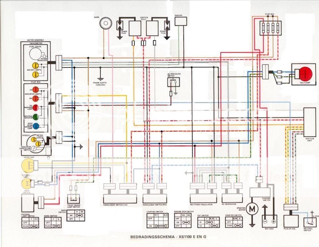
    I have three extra wire that I am trying to figure out where they go or which to get rid of...below are the three wires and the wiring diagram I am using. I just need one of these three red wires and I will splice the wire for all the extra places it will go. One of them has a bullet connector and I am guessing that is the one that, on the stock wiring diagram, goes to the starter...The other two in the stock wiring diagram, go to a resistor and then back to themselves and the start switch...Can someone tell me which wire i need to use to follow this wiring diagram?

    Thanks

    -Rick


    1979 XS1100 Standard

  • #2
    Am I to understand that you're creating your own wiring scheme and you're asking us which wires you need and which wires you don't need?

    Huh?

    Comment


    • #3
      No, I am tearing apart the wiring harness and slicing NEW wires in place of old melted ones. On the wiring diagram there are three red wires coming off the ignition unit. I have already figured out what the grey orange black/white and black wires are for, I just need to figure out which red wire goes to the pos coil and starter switch. I figured out that it probably isn't the red and yellow so that leaves two red and white ones. One is mainly red with a white stripe and the other is mainly white with a red stripe. Does that make more sense?

      Sorry for the confusion...

      -Rick
      1979 XS1100 Standard

      Comment


      • #4
        Use an ohmmeter to trace the wires

        Comment


        • #5
          Lost without a trace....

          I second using the ohm-meter to trace the existing red wires. It is a skill that will pay off both now and later down the road. In this "tracing" it is important to actually disconnect the battery and then the red wires from whatever they are connected to. Then make sure that the "ohm/continuity" test shows that the red wire ends are connected/show continuity between the two ends you are testing and only to those two ends. (Surprises with electricity/wires are most often accompanied my melting/smoke...)

          As far as eliminating "unnecessary/redundant" wires there are two complications I see. First, each wire has an amount of current it must carry to whatever it is connected to and so it may be that when you consolidate/share the same wire to more devices than original there may be a voltage drop at the ends. (Bad..) Second, the original wiring diagram which any other person would refer to in order to troubleshoot would be invalid. You could fix this by making your own revised diagram and keeping it with the bike. Most PO's seem to not follow this practice and so the new owners have to rediscover any "modifications" the hard way: in the dark while out of town on what they thought was going to be the perfect ride.

          Good Hunting!

          Comment


          • #6
            Thanks for the tips guys! I was going to just use the existing harness but it was a nightmare due to shotty wiring from the po. So now I am into this lengthy endevor! Thanks for the help...

            -Rick
            1979 XS1100 Standard

            Comment


            • #7
              If the PO really went to town on your wiring and you're in deep then taking a look-see at another XS1100's wiring saves a lot of "re-inventing the wheel." It's one of those situations where copying doesn't count as cheating. Plus there's just so many details about what is connected to what and how the wires are actually routed.

              Network: May be someone in your area has a functional XS and if they can't take a ride over on a sunny day then you can meet and take some useful photos. Amazing just how cooperative XS owners can be....

              Comment


              • #8
                Doh!

                AND...I figured it out! I need to plug in the white/red wire to the coils, then branch it off, and splice it to the red/white wire(which would have been done with the the ballast resistor, but since I did the upgrade, it is no longer needed) which will then go to the starter button, and then on it's way back to the ignition unit, it will splice off that to the starter and then finally to the ignition unit! Bright light just clicked on in my mind! It was much simpler when I finally did the ohm testing, and looked at a better wiring diagram! The one i have is from the manual and it is just black and white. It is much easier to read if it is in color!

                Thanks again!

                -Rick
                1979 XS1100 Standard

                Comment

                Working...
                X