
i just got done reading this post and i really like the idea of FI, Is this a fuel pump you could use? there is a graph at the bottom of the page that shows
Fuel Pump Performance Curve Chart
http://cgi.ebay.com/ebaymotors/89-94...Q5fAccessories
-
Bad new; today's testing revealed that the wonderfully small LTR fuel pump is just that, too small. For all the sceptics out there, you were right. I borrowed a friend's fuel injection pressure gauge and plumbed it in. WOT at 5-6, the pressure started dropping off, and by 7+, the pressure had dropped to the mid-high 20's. Looks like it's back to the drawing board for a fuel pump
Leave a comment:
-
I would say, that the clearance might prove to be something one might need to adjust. I spent a lot of time shimming to get what I thought was just the right clearance between the wheel and the sensor. The actual timing postition isn't as important. Other than during start up cranking, the base timing is totally adjustable through software. During cranking, my bike fires at TDC, because that is where I mounted my sensor relative to the wheel.Leave a comment:
-
Is it possible to mount that sensor on the stock adjusting assembly? I read on one of these EFI threads that alignment of the trigger wheel and the sensor is tres important, so having an adjustment could make life easier?Leave a comment:
-
I did a quick search, and found it for $25. Here is the exact one I used.Leave a comment:
-
I spent TONS of time looking around. Everywhere around. I looked throught the suppliers book at the auto parts store for over an hour. Everytime I would find one that looked promising, it was VERY pricy. Ultimately, while perusing eBay with very general searches like "(vr,crank,position) sensor", I found this one. However, it has been so long that I don't remember for sure what it came from. It was brand new and only cost me around $30. I think that it may have come from either a newer VW or Audi. I am REALLY mad at myself for not making a note of what vehicles it was designed for. I will look through my ebay records and see if I can dig up something more specific.Leave a comment:
-
-
I think it will be okay. It handled 211 deg F just fine. The highest my sensor in the fins has gotten was 215. That was sitting in my garage syncing the TB's and running a box fan.Leave a comment:
-
The sensor looks aok and you're right about them being fragile.Heat sink compound can be placed between the thermistor and what ever you are mounting it to.This allows more efficient heat transfer and keeps the contact point from becoming oxidized.Great job on your injection system. Terry
Terry
Leave a comment:
-
is there an upper temp limit the thermistor can handle? will the head temp exceed that limit?Leave a comment:
-
Megasquirt uses a CLT (Coolant Temp) sensor to monitor engine temperature. The only real purpose of this is for enrichment during the warmup period. For air-cooled vehicles, this can prove to be a challenging feature. In Stan's build, he uses the standard GM CLT sensor and wedges it between the fins of the head for monitoring the temp of the head as this is a good alternative to actual coolant temps. With my setup, the only good place I could get this same scenario to work out was in the fins of the cylinders. I didn't like it from the start. Then, while datalogging for tuning purposes, it repeatedly fell out. This dropped the temp values which sent the bike back into warmup enrichment, which in turn caused MLV (MegaLogViewer) to filter out 90+% of my data.
So, following on the coat tails of a guy who MS'ed his '71 911 porsche, I decided to make my own Head Temp Sensor.
I stopped at a computer shop on my way home and picked up an old, junk power supply and upon arriving home, disassembled it.
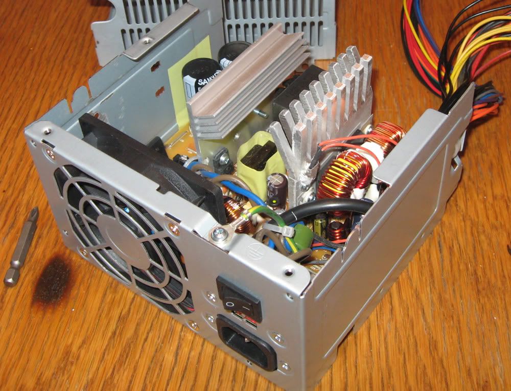
Here is a close up of the thermistor in place on the aluminum heatsink.

Here is the thermistor removed next to the washer connector I mounted it in.
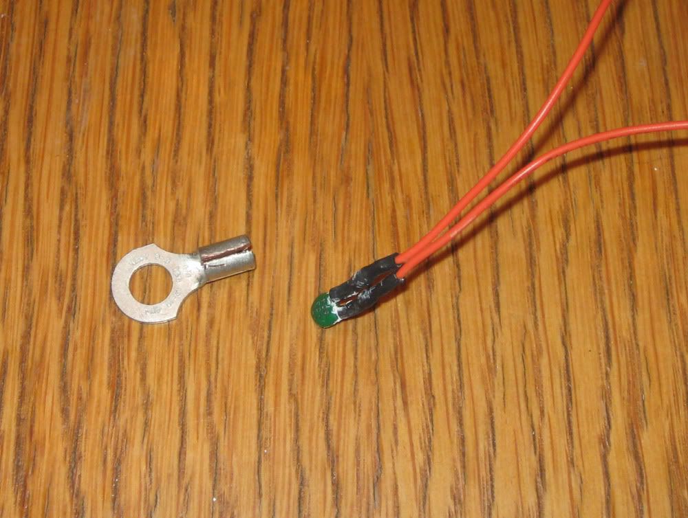
I opened up the connector, split it, and carefully secured it. Appearently, thermistors are fragile, so you can't just mash it tight.
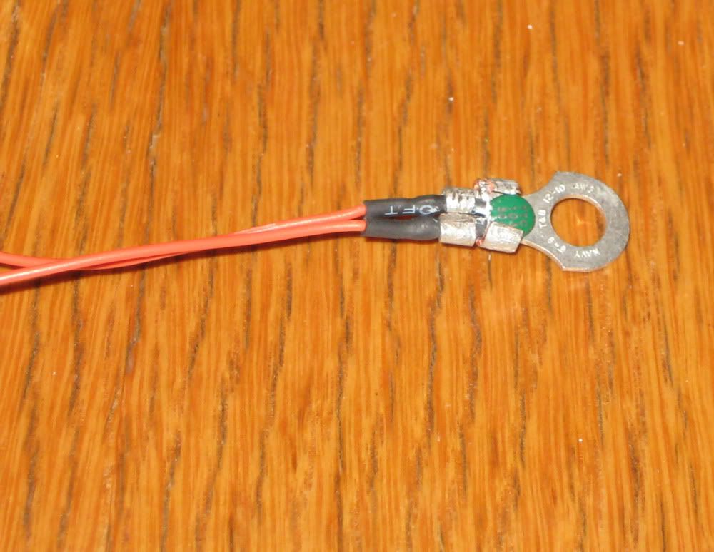
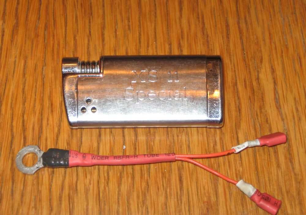
Once it was snug, I JB Welded it in place, added connectors, and heat-shinked it. Here is the final product. Initial testing showed it was quickly responsive to the addition of mere finger temps from the application of thumb and pointer squeezed. Notice my 'special' lighter for scale. SWMBO got it for me a few years ago.
After the assembly was complete, I needed some resistance values to calibrate it as it is different than the standard GM CLT sensor MS is set up for. The MegaTune program makes it simple. You just need 3 resistance values with corresponding temperatures. Going for the obvious and most stable, I chose to do ice water (shown below) at 33 deg F, boiling at 211 deg F, and room temp at 70 deg F.

Tomorrow, I will mount the new sensor to the center-rear valve cover bolt. It is out of the airflow and should be a nice location for head temps.
Hope you all enjoyed the pics and story time. I will gather some more pics during the install and share.Last edited by Ken Talbot; 05-04-2009, 11:33 PM.Leave a comment:


Leave a comment: