Announcement

Collapse
No announcement yet.

Yet another plea for electronics help!

Collapse
X
 
  • Filter
  • Time
  • Show
Clear All
new posts

  • Yet another plea for electronics help!

    Hey folks,

    Been a few weeks since I've been on, took a vacation to visit MOM, and HS best friend in Texas and such, then just took some time OFF from the "site" to further recharge the brain cells!

    Anyways, I have 2 professional grade editting VCR's that I "acquired" from my previous employer when he retired, they are Panasonic AG-1960's, decent decks. But last year, 1 of them died....blew 240V volt fuse, not the 110V one. Replaced it and it immediately blew when plugged in. Then this year, the second one died, same way, same symptoms.

    Searched the "NET", found a VCR repair newsgroup listing/digest, talked about a voltage regulator that often fries, they described it with 5 pins to the circuit board, but all had dark brown look to the solder joints, like they had gotten overheated. They replaced this component along with a LARGE capacitor, and theirs was working again.

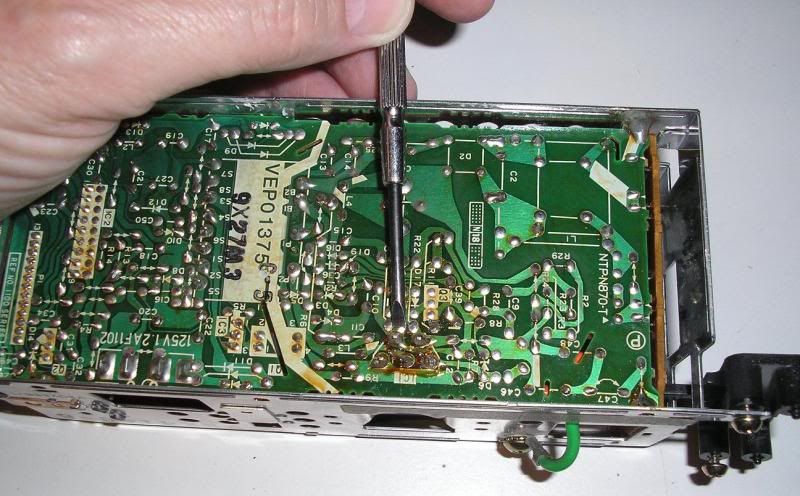
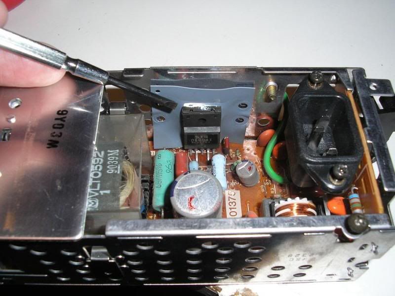
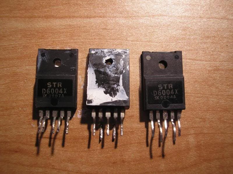
    So..I took mine apart, pulled the Power Supply, found the same regulator chip, 5 pins, with heat sink conductive paste on it to a ?rubber? heatsink plate. Found model #... STR D6004X, found site on line that supplied them, only $3.99 ea, got 3 because of $10.00 min. order. Desoldered old ones, put new ones in with fresh thermal paste and VIOLA, the units powered back up, and seemed to run fine. However, after 15 minutes, they powered OFF, then after a cooling period would power back up again, so looks like an overheat protection circuit in the regulators??

    I did NOT replace the large Capacitor because it didn't look SWOLLEN or blown? However, the newsgroup digest talked about ESR values for it being out of spec? I don't know or have an ESR gauge, or how to use one??

    There is a VCR repair place just a mile from my house. I'm tempted to take the Power Supply there, and see if they could do the ESR test on the capacitor or such to see what other component apparently needs replacing to prevent the overheating of the voltage regulator that I installed!?

    Here are a few photos of the power supply, circuit board, voltage regulator component, etc.! Any electronics GURU's out there with any hints? I don't have a schematic, but wouldn't know how to read it anyways, I'm lucky to be able to follow basic +/- paths, but not caps, resistors, IC's etc.!

    T.C.


    T. C. Gresham
    81SH "Godzilla" . . .1179cc super-rat.
    79SF "The Teacher" . . .basket case!
    History shows again and again,
    How nature points out the folly of men!

  • #2
    Usually if a cap has ESR problem it will work when it's warm but not cold.It's always a good idea to replace electrolytics in question but I'm willing to bet you have an open resister across the regulator causing the regulator to pass to much current and over heating.Check and see if there is a low value resister across pins 1 and 3 or pins 1 and 5 of the regulator.

    Terry
    1980 special (Phyllis)
    1196 10.5 to 1 kit,megacycle cams,shaved head,dynojet carb kit,ported intake and exhaust,mac 4 into 1 exhaust,drilled rotors,ss brake lines,pods,mikes xs green coils,iridium plugs,led lights,throttle lock,progressive shocks,oil cooler,ajustable cam gears,HD valve springs,Vmax tensioner mod

    Comment


    • #3
      The caps are CHEAP! two pins, and be sure they go in correctly, as they DO have a positive and negative lead! put one in backwards and it will go POP!!. DAMHIKIJK Radio shack should have the caps, and I would replace the smaller one as well, just to be sure. DO check that the voltage on the new cap is at least as high as the voltage on the old cap.
      Ray Matteis
      KE6NHG
      XS1100 E '78 (winter project)
      XS1100 SF Bob Jones worked on it!

      Comment


      • #4
        Did you get a data sheet with the regulator? If you did check what the rated I/O voltages should be, and on what pins, and measure them in the working circuit. As Ray said, caps are cheap and should be replaced as well. They dont have to be very far out of spec to cause problems. TW is also correct in referring to any resistors across the regulator, but a failed resistor is usually fairly obvious and easy to spot.
        1980 SG. (Sold - waiting on replacement)
        2000 XJR1300. The Real modern XS11. Others are just pretenders.

        Woman (well, my wife anyway) are always on Transmit and never Receive.

        "A man should look for what is, and not for what he thinks should be" Albert Einstien.

        Comment


        • #5
          If it's powering up and then shutting off, it could be due to the regs over heating. Check that you've thermally bonded the chips to the heatsink.

          Power supply caps are a weak point, and it's worth replacing them. But if ESR caps are required, it's important that ESR caps are used. You may not be able to pick them up at RS for example. They will cost a bit extra, but not much. You can use higher voltage ones than specified and check the temperature ratings, higher is better.

          Jaycar now are in the US. They seem to have decent quality components here and I guess their US based stores use the same suppliers.
          XS1100G (3X1 000274) "Torquey"

          You can think of a lightning bolt as essentially a really really big bug zapper. Unfortunatey, we're the bugs.

          Comment


          • #6
            Followup info and questions.

            Thanks folks,

            Okay, I don't know which pins are which on the reg, I DID replace both regs one on each PWS, see the last photos.

            I tested the spare new one, and it showed 2M ohms across a couple of pairs of pins....
            (-) (-)
            - (-) - I tried to make an ascii type drawing here, the pins in parantheses were the ones that showed values.

            The old burnt regs only showed a few ohms....not Meg ohms!

            I spoke to and showed the VCR guy...some old Russian immigrant that's been there for decades, and he said since the PWS was almost as old as him , to replace ALL of the caps! However, there are 14 of them, several hidden under that large plate under my hand/finger as well as 4 others at that end of the circuit board.

            Yes, I did use thermal paste when I put the replacement regs in place.

            So....you guys think I really need to replace ALL of the caps....they are close to 20 years old though HUH?!

            I found and notated as well as photographed it, the polarity marks on the tops of the caps for when I get to putting the new ones back in. I'll post in a moment the ranges of their powers..voltages...uF, Temps etc.
            T.C.
            T. C. Gresham
            81SH "Godzilla" . . .1179cc super-rat.
            79SF "The Teacher" . . .basket case!
            History shows again and again,
            How nature points out the folly of men!

            Comment


            • #7
              T.C., the caps could have dried out. They won't swell if there's little or no electrolyte left in them, they'll just short, burn and explode or go open-circuit. Either way it stops being a capacitor.

              Another thing to look at is the heat sink. The back side of the regulator is probably electrically 'live' and the rubberized heat sink is a thermal pad/insulator to keep the regulator from shorting to the metal case.

              In the second picture showing the components I see a gap between the heat sink and the metal case. Were the old regulators up against the metal case or more freestanding like they are now with just the ends of the heat sink screwed down to the metal case?

              If that is rubber it won't dissipate heat very well by itself so it should be against something else to transfer heat, like the thermal pad between a CPU and its heat sink.
              -- Scott
              _____

              2004 ST1300A: No name... yet
              1982 XJ1100J: "Baby" SS Brakes, '850 FD, ACCT
              1980 XS1100G: "Columbo" SS Brakes, '850 FD, ACCT
              1979 XS1100SF: "Bush" W.I.P.
              1979 XS1100F: parts
              2018 Heritage Softail Classic 117 FLHCS SE: "Nanuk" It's DEAD, it's not just resting. It is an EX cycle.

              Comment


              • #8
                Thanks Scott,

                The lightbulb just went on over my head! I now understand the purpose of the electrolyte in the capacitors. I suspect the large one which is rated at 100uF, 250V and 105 degrees C is a likely one, it's the one that the repair Digest stated they replaced along with the regulator.

                If you'll look at the top photo...where the burnt solder ends were on the reg, the PWS case has a recess towards the regulator. The second photo shows HOLES in the rubber film, theres a big clamp that pushes/holds the Reg against the film and against the protruding case, so the case does work as a heatsink with the rubber film and thermal paste. I didn't know that the case of the reg was conductive? BTW, there wasn't any paste on the side of the rubber film and the case, would it be helpful to put some between there as well as between the regulator and film?

                Is there a way I can test the caps with a simple Volt/Ohm/Ammeter???

                T.C.
                T. C. Gresham
                81SH "Godzilla" . . .1179cc super-rat.
                79SF "The Teacher" . . .basket case!
                History shows again and again,
                How nature points out the folly of men!

                Comment


                • #9
                  Originally posted by TopCatGr58 View Post
                  Thanks Scott,

                  The lightbulb just went on over my head! I now understand the purpose of the electrolyte in the capacitors. I suspect the large one which is rated at 100uF, 250V and 105 degrees C is a likely one, it's the one that the repair Digest stated they replaced along with the regulator.

                  If you'll look at the top photo...where the burnt solder ends were on the reg, the PWS case has a recess towards the regulator. The second photo shows HOLES in the rubber film, theres a big clamp that pushes/holds the Reg against the film and against the protruding case, so the case does work as a heatsink with the rubber film and thermal paste. I didn't know that the case of the reg was conductive? BTW, there wasn't any paste on the side of the rubber film and the case, would it be helpful to put some between there as well as between the regulator and film?

                  Is there a way I can test the caps with a simple Volt/Ohm/Ammeter???

                  T.C.
                  +1 on replacing the capacitors.

                  I also would recommend that thermal paste be used on both sides of the rubber insulator. I would also recommend something like arctic silver rather than the bottom of the line stuff. I know it's not what was originally there, but the silver powder in it increases it's heat conduction which is the point. If it were me, I'd be trying to find a mica insulator to replace the rubber one with, as the mica does as good a job at insulating, but is MUCH better at heat conduction, often used without the paste even. But then I've always believed in overkill, especially in electronics. I can't say in all the years I've worked with electronics (since high school frankly) that I have ever see to good of a job of heat conduction when cooling something (well maybe if the conduction was to something you can touch on the outside of the case ), as the lower you keep the temp, the longer the part will last. The darkening of the board and such around that component tells me that it wasn't really designed with enough cooling, and the fact that it failed on TWO units at least points to that issue. So anything you can do to increase cooling is going to make it run better and last longer.
                  Cy

                  1980 XS1100G (Brutus) w/81H Engine
                  Duplicolor Mirage Paint Job (Purple/Green)
                  Vetter Windjammer IV
                  Vetter hard bags & Trunk
                  OEM Luggage Rack
                  Jardine Spaghetti 4-2 exhaust system
                  Spade Fuse Box
                  Turn Signal Auto Cancel Mod
                  750 FD Mod
                  TC Spin on Oil Filter Adapter (temp removed)
                  XJ1100 Front Footpegs
                  XJ1100 Shocks

                  I was always taught to respect my elders, but it keeps getting harder to find one.

                  Comment


                  • #10
                    T.C., the back of the regulator IC may or may not be 'live' but I'd bet it is because they used an insulator. To know for sure you would have to look at the datasheet from the manufacturer.

                    The electrolyte, usually a glycol-based liquid saturated with conductive ions, is carried by a strip of paper soaked in the stuff and forms one 'plate' of the capacitor. A strip of specially-oxidized aluminum forms the other plate and that oxide forms the dielectric barrier to keep the aluminum substrate physically separated from the electrolyte.

                    Basically, it's a can stuffed with rusty aluminum and newspaper soaked with rusty brake fluid.


                    You can test capacitors for simple short or open conditions and a several other things with a multimeter but it's not a complete test. It's a lot easier to replace the cap. Here's a link to the sci.electronics.repair newsgroup FAQ

                    By the time you finish reading the FAQ you could have driven to Radio Shack and back home, replaced the fishy caps and, hopefully, be watching movies on both of your VCRs.


                    +1 for what Cy and the other members have written. Also, take off all watches, rings and dogtags/necklaces/jewelry, then make sure the unit is not plugged in and the capacitors are discharged before you stick fingers, multimeter probes or a soldering iron into a power supply.

                    I know it's not going to happen but ideally you should be using an isolation transformer if you're going to play with power supplies and not just plugging into the wall: a current-limiting AC isolation transformer vs an instantaneous 50-zillion Amps from the Grand Coulée Dam and straight out of the socket before something in the circuit gives up, usually the breaker or a fuse but sometimes the tester!
                    -- Scott
                    _____

                    2004 ST1300A: No name... yet
                    1982 XJ1100J: "Baby" SS Brakes, '850 FD, ACCT
                    1980 XS1100G: "Columbo" SS Brakes, '850 FD, ACCT
                    1979 XS1100SF: "Bush" W.I.P.
                    1979 XS1100F: parts
                    2018 Heritage Softail Classic 117 FLHCS SE: "Nanuk" It's DEAD, it's not just resting. It is an EX cycle.

                    Comment


                    • #11
                      A few more questions PLEASE?

                      Thanks for the Link Scott,

                      Interesting info for sure, I did check some of it out.
                      The most dangerous cap (I think?) the 100uF@250V has already been removed. I've used my DMM to test voltages on the other caps thereby discharging them in the process.

                      As for Radio Shack, they don't have the variety that I seem to need. Here's the rundown on uF and Voltages.
                      100uF@250V
                      1uF@200V
                      **56uF; 10uF; 100uF @ 50V
                      **1200uF@20V
                      47uF; 10uF @ 16V
                      100uF; 680uF @10V
                      470uF @ 6.3V

                      I have found an online source in the US that can provide most of these, however the ones I marked with ** are not exact matches. From what had been stated before, I could/can use the same uF of a slightly higher Voltage and be OK?

                      The 1200uF were@20V, I found 25V, so I would think that would be OK?

                      The bigger problem I see is that I can only find 47uF@50V, or
                      47uF or 68uF @ 63V??

                      I'm trying to order all of these from the same source for both price and shipping. So far the total $ is about $13.00 for BOTH PWS's, minus the 47Uf/50V ones...1 per PWS, but the 68uF/63V are 0.48 ea., so looks like I would be able to get them all for less than $15.00 plus shipping!

                      So...can you or someone advise me on what the substitute values for the 2 caps in question would be so I can complete/place the order?!

                      T.C.
                      T. C. Gresham
                      81SH "Godzilla" . . .1179cc super-rat.
                      79SF "The Teacher" . . .basket case!
                      History shows again and again,
                      How nature points out the folly of men!

                      Comment


                      • #12
                        Yeah, the 25V will be ok. As long as the voltage (or temp) rating is equal to or higher than the requirements, you're ok

                        There is a rule of thumb about replacing capacitors, but I can't remember it
                        It's because their tolerances are so bad, so usually one size either direction doesn't cause problems, but it varies with the circuit's requirements. But I can't remember if you go down or up.

                        Remember to check the temp ratings and whether low ESR (Equivalent Series Resistance) are needed.

                        Sorry I can't give you a better answer.
                        XS1100G (3X1 000274) "Torquey"

                        You can think of a lightning bolt as essentially a really really big bug zapper. Unfortunatey, we're the bugs.

                        Comment


                        • #13
                          Originally posted by TopCatGr58 View Post
                          From what had been stated before, I could/can use the same uF of a slightly higher Voltage and be OK?
                          Try to stick with the existing capacitances and go up to the next (sane) available voltage.

                          1200uF@25V and 47uF@50V will be fine. With electrolytics you can go with slightly larger capacitances and higher voltages for a power supply filter. Most of the time the design is a compromise made to save money and build a safe device, or at least one that is less likely to fail and burst into flames when Purchasing finds a great deal on a mystery ship filled with inscrutable mystery caps.

                          You should write down any changes you made inside the VCR cover, mostly so that you'll remember what in heck you did. That would be a handy piece of information to have right there for a future owner/tech considering the same trick you did so they don't substitute even larger caps.


                          Be careful! Don't be fooled by the deceptively-low voltages in a consumer power supply. Amperage is what gets you, not voltage.

                          Unplug, test/modify, power up.
                          Unplug, test/modify, power up.
                          Unplug, test/modify, power up.
                          Check a reference book or go outside to see what on Earth the kids are up to now.
                          Test/modi-ZAP!
                          -- Scott
                          _____

                          2004 ST1300A: No name... yet
                          1982 XJ1100J: "Baby" SS Brakes, '850 FD, ACCT
                          1980 XS1100G: "Columbo" SS Brakes, '850 FD, ACCT
                          1979 XS1100SF: "Bush" W.I.P.
                          1979 XS1100F: parts
                          2018 Heritage Softail Classic 117 FLHCS SE: "Nanuk" It's DEAD, it's not just resting. It is an EX cycle.

                          Comment


                          • #14
                            Followup update.

                            Well, when I received the batch of caps, I was surprised with a few. The 1200uF ones were at 35V instead of 20 or 25, and the 470uF at 6.3(six pt three) ended up at 63 volts ! But I wanted to put it back together, so I went ahead and put them in, they had the proper uF, the 63volt one was a bit larger in diameter than the OEM 6.3, but I had enough room to put it in.

                            Anyways, got them all soldered in and in the right position/polarity, and put it all together, plugged it in, and viola, it worked. Left it on first for 30 minutes, and it kept working. I set the clock, and then left it on overnight, got up the next morning, and it was still ON and the clock was correct!

                            I think the new Volt. Reg. was just overheating too much due to the bad caps, and once it had good ones, then it was able to function properly and not get overheated.

                            I oopsed and ordered 2 few of the 47uF/50V ones, so I can't fix the second deck, yet....will be getting them from Ebay in a few days!

                            SO...just wanted to give a big final thankyou to all who contributed to this thread, and my ever enlarging knowledge base of electronics....essentially knew nothing so no where to go but UP!

                            THANKS!!!
                            T.C.
                            T. C. Gresham
                            81SH "Godzilla" . . .1179cc super-rat.
                            79SF "The Teacher" . . .basket case!
                            History shows again and again,
                            How nature points out the folly of men!

                            Comment


                            • #15
                              Good to hear TC. At last, my 3 years of educations in electronics paid off. It only took 25+ years
                              XS1100G (3X1 000274) "Torquey"

                              You can think of a lightning bolt as essentially a really really big bug zapper. Unfortunatey, we're the bugs.

                              Comment

                              Working...
                              X