Anatomy of the Carbs

Collapse
X
 
  • Time
  • Show
Clear All
new posts

  • TopCatGr58
    replied
    MORE carb Porn!!!

    Hey Scott,

    Well, yeah, you would think that since the air mixing port is after the pilot jet, that the different actual JET would not make any difference provided the actual jet orifice size is the same...ie. 42.5, so I can't explain it either. I can show though that there isn't any hidden air mixing port....just the same one that I showed in the previous lengthwise sliced view of the 78-79 series carb. I got slice happy today and went ahead and sliced the other 3 carb bodies he/Grant had sent me for dissection. Along with the 80-81, I also CROSSCUT the 78-79 right at the pilot jet tower so you can see the slanted upward path it takes AROUND the carb tunnel to get up to the pilot jet tunnel along the top of the carb throat. And again....there's only 1 location for the AIR to get into the pilot jet circuit....right after the pilot jet!! Note the little brass PLUG on the other END of the slanted pilot jet tunnel! Okay, here are the photos! Oh...I also corrected my previous comparison photos I did so I'm including them as well FIRST.
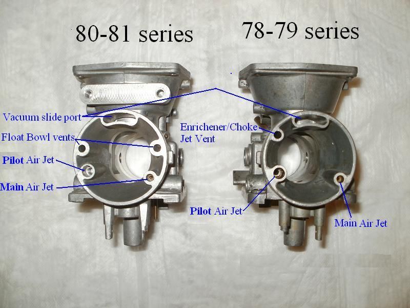
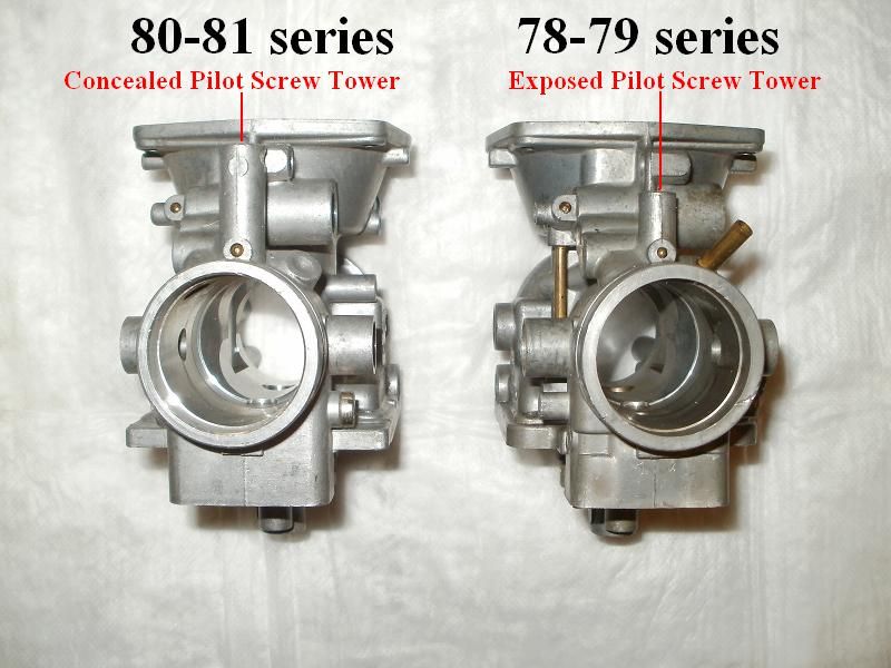
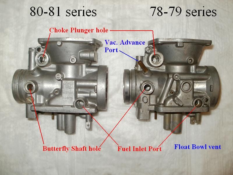
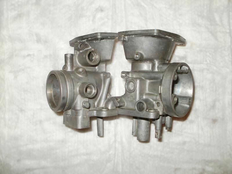


    It's hard to see it, but there's a brass cap on the end of the slanted tunnel going up and to the left on the left half. The hole above it is the tunnel for the CHOKE/Enrichener tunnel that goes down towards the edge where the float bowl connects!
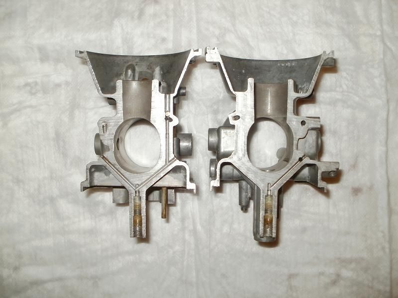

    80-81 carb sliced lengthwise
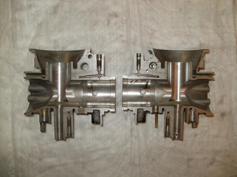

    80-81 carb sliced CROSSWISE
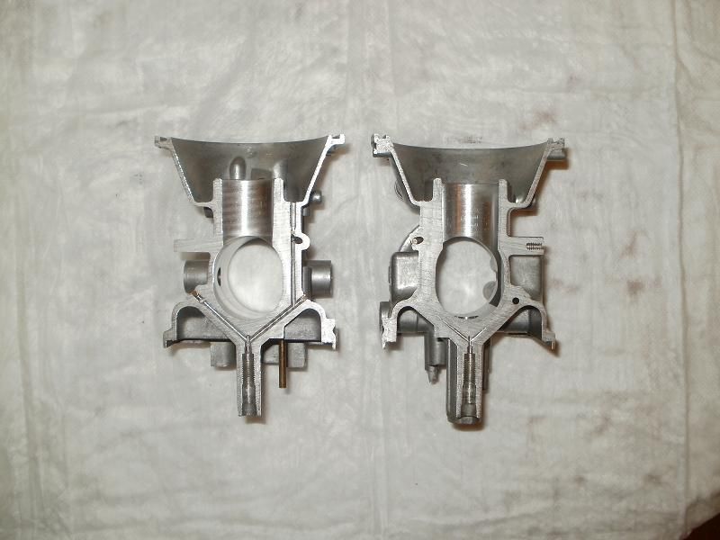

    T.C.

    Leave a comment:


  • 3Phase
    replied
    T.C.,

    There are three types of jets. The VM22 jets have the fuel metering hole at the top, the BS30/96 jets and the N151 have the hole at the bottom.

    Unless there's a stealth Pilot Air passage that's drilled into the cavity around the Pilot Fuel jet to let air into the bleed holes I have no idea why it makes any difference in the XS11 carbs. Mikuni jets are supposed to be sized by fuel flow so with no air to the bleed holes a 42.5 should be a 42.5 should be a 42.5 whether it's a VM, a BS or a N151. Apparently, "It ain't necessarily so!"

    .

    Leave a comment:


  • TopCatGr58
    replied
    Well, aside from George,

    MikesXS apparently knew this as well....several years ago, I remember posting this quote from their website some time ago!


    Note: BS 30/96 type Pilot Jets WITH Side bleed holes and those without side bleed holes are completely interchangeable.
    Some time back "we" thought that we had learned that the wrong # of vent holes in the sides of the pilot jets were a part of the overly rich problem we've experienced, but that apparently was a red herring! The wrong # of side holes WAS a way to tell that a person may have NON-genuine Mikuni jets, and that it was the variance in the size of the metering holes in the After Market jets vs. the Mikuni along with the LOCATION of the metering orifice being proximal to the screw end vs. the tip/taper end that also causes problems.

    Feeling like a lucky punk!

    T.C.

    Leave a comment:


  • BA80
    replied
    Make my day.................

    Leave a comment:


  • 3Phase
    replied
    Originally posted by SFerinTEXAS
    the silence is deafening. bump.
    What are you expecting? A fuel duel at high 'noon between the N151.067 and BS30/96 with sharpened mixture screws at twenty paces?

    .

    Leave a comment:


  • SFerinTEXAS
    replied
    the silence is deafening. bump.

    Leave a comment:


  • GLoweVA
    replied
    Originally posted by WMarshy
    Not true, they still matter because they effect how much fuel becomes atomized and carried downstream through the pilot needle.
    I've got non holed pilot jets (42.5) in my H and they work fine.

    The side holes make no difference in how much or how "turbulent" the flow is. The metered end is what matters.

    Thanks TC for definitely showing what I figured out over a year ago.

    Leave a comment:


  • SFerinTEXAS
    replied
    Glad to know the world is flat.

    Leave a comment:


  • WMarshy
    replied
    Originally posted by SFerinTEXAS
    excellent work T C. Sooo the world is not flat and all the fuss about the pilot jet bleed holes has apparently been upset.
    Not true, they still matter because they effect how much fuel becomes atomized and carried downstream through the pilot needle.

    Leave a comment:


  • SFerinTEXAS
    replied
    Pilot Jet Air inlet is AFTER the Pilot Jet in the pilot jet circuit.
    excellent work T C. Sooo the world is not flat and all the fuss about the pilot jet bleed holes has apparently been upset.

    Leave a comment:


  • 3Phase
    replied
    Nice work, T.C.!

    It would be interesting to see a sliced and diced XJ11 carburetor....

    The XJ11 uses slightly larger and richer Mikuni N151.067 47.5 Pilot Jets with no air holes and they work fine. The XS11 uses Mikuni BS30/96 42.5 Pilot Jets with the air holes and some members have had problems after trying the N151 jets. I know they'll fit but I wonder if the N151 47.5 jets would work for the XS11 instead of the BS30/96 42.5 jets. I'll have to get my XS running again and experiment.

    For the XS1100 carburetors:

    The Pilot Air passage joins the outlet of the Pilot Fuel Jet and forms the beginning of the Pilot Fuel/Air Circuit. The Pilot/Mixture screw is downstream from the junction of Pilot Fuel/Air passages so the screw controls the amount of premixed fuel and air that can pass through its Idle Port.

    The three holes in the carburetor throat just upstream of the Throttle Plate are the Transition Ports. The Transition Ports are progressively uncovered as the throttle is opened and the carburetor transitions from Idle to Low Speed operation.

    The amount of premixed Fuel/Air for the Transition Ports and it's ratio is controlled by the size of Pilot Fuel and Air jets, the size of the Pilot Air and Fuel passages, the size of the Pilot Fuel/Air passage and by the size of the three Transition Ports.

    The Pilot/Mixture screw is downstream from the Transition Ports and cannot affect them unless you drill out the Idle Port and basically overwhelm the Pilot Fuel/Air Circuit.


    .

    Leave a comment:


  • James England
    replied
    I love it! How about a little suggestion? Paint the sawn edges blue or red or whatever, to make everything else stand out...I saw it in a museum on a steam engine and a jet engine....it looks nice.

    In any event, I bet you felt great starting up the bandsaw!

    Leave a comment:


  • skids
    replied
    It is interesting! There are a lot of complicated pathways for both air and fuel...

    Leave a comment:


  • TopCatGr58
    started a topic Anatomy of the Carbs

    Anatomy of the Carbs

    Hey there Folks,

    Okay, this will eventually get turned into a tech tip of some sorts, but wanted to get a few of these posted ASAP! Mack was nice enough to send me 2 pairs of otherwise trashed carb bodies, 2 of the 78-79, 2 of the 80-81 series. I took a bunch of photos showing the 2 different kinds side by side. But the most FUN part was putting a carb on my BAND SAW and slicing right through one vertically front to back!

    The following photos are just a few I've prepared with labels and such. The 1st 3 are 800 x 600 size, the last one is larger ~1150 x 750 to reveal the details a bit better, but our site resizes them to fit into the web page view, remember you can click on the image to see the full sized version.

    I also did a bunch of poking and prodding, blowing thru passages and such to determine the pathways, and was actually came up with a few surprises!!!

    Darnit, I just realized that I made a mistake in my labelling of the photo that shows the INLET ports view....I'll fix it and then I'll post it later.

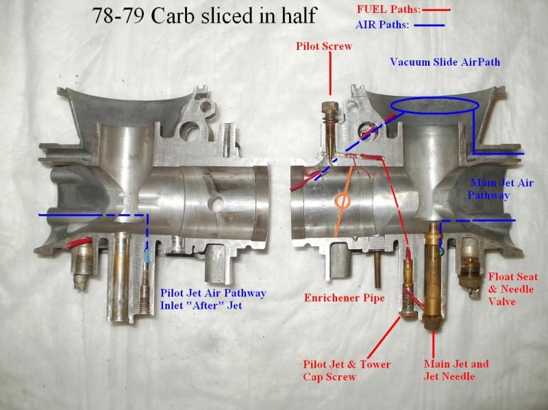
    Anyways, here's the SPLIT VIEW. I tried to outline the Fuel and Air pathways with RED and BLUE to more easily differentiate them.

    The Large Choke/Enrichener port is a dual function port. When the Choke is pulled, it routes fuel from the Bowl up and thru the port, but when the Choke is closed, that port is involved in the air flow for the vac. slide!

    The other interesting things are, note the MAIN JET Air port is in the emulsion tube tunnel up near the carb throat. However, the Pilot Jet Air inlet is AFTER the Pilot Jet in the pilot jet circuit. What's also interesting is that the 3 little ports in the top of the carb throat are positioned BEFORE the butterfly valve. The Pilot SCREW is after the butterfly. But also the pilot screw is controlling both AIR and FUEL since the Pilot circuit fuel is being mixed with air just after the Pilot Jet, and way before the Pilot screw. So it appears that it does NOT just adjust FUEL alone, but fuel and air!


    Anyways, more to come, but thought folks would find this interesting!

    T.C.
Working...